


F-54
TROUBLESHOOTING & REPAIR
F-54
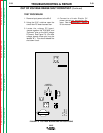
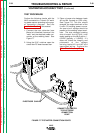
5. Start welding and observe the
ACTUAL voltage reading on the NA-
5 digital meter. The actual voltage
must match the SET voltage within
+/- 0.5VDC. If it does NOT, the NA-
5 is designed to shut down.
6. If the NA-5 continues to shut down
with the "BYPASS" pins jumpered
together, the voltage PC board may
be faulty.
7. If the ACTUAL voltage reading is
zero, the sensing leads may be
faulty. Perform the
External
Resistance Test
. Also check the
1/8 amp fuse on the voltage PC
board.
8. Check the polarity switche in the
Lincoln power source and its associ-
ated leads. Set the switches to the
same polarity as the electrode. See
the Wiring Diagram.
9. If the ACTUAL voltage reading is dif-
ferent from the SET voltage reading,
the power source may not be capa-
ble of producing the required arc
voltage, the control cable may be
faulty or misconnected, or the NA-5
voltage PC board may be faulty.
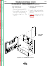
10. After all tests are complete, remove
the input power to the wire feeder
and remove the jumper wire you
placed on the "BYPASS' pins on
the voltage PC board. Close and
secure the access door.
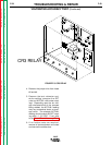
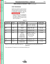
OUT OF VOLTAGE RANGE SHUT DOWN TEST (Continued)
NA-5
Return to Section TOC Return to Section TOC Return to Section TOC Return to Section TOC
Return to Master TOC Return to Master TOC Return to Master TOC Return to Master TOC