


F-5
TROUBLESHOOTING & REPAIR
F-5
NA-5
Observe all Safety Guidelines detailed throughout this manual
If for any reason you do not understand the test procedures or are unable to perform the tests/repairs safely, contact the Lincoln Electric
Service Department for technical troubleshooting assistance before you proceed. Call 216-383-2531 or 1-800-833-9353.
CAUTION
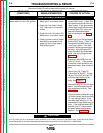
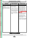
WIRE FEEDING PROBLEMS
PROBLEMS
(SYMPTOMS)
POSSIBLE AREAS OF
MISADJUSTMENTS(S)
RECOMMENDED
COURSE OF ACTION
The wire does not feed. Pressing
any of the switches (buttons) will
NOT feed the wire. The motor does
NOT run.
1. Make sure input power switch is
ON.
2. Check the circuit breaker (CB1).
Reset if tripped.
3. Make sure 115VAC is being
applied to the control box through
the control cable receptacle.
Leads #31 and #32.
4. Check the two fuses on the
power board. Replace if blown. If
fuse F101 immediately fails when
replaced contact your local
Lincoln Authorized Field Service
Facility.
5. Make sure the motor cable is con-
nected to the motor receptacle on
the NA-5 control box.
1. Check the lights (LEDS) locate on
the PC boards. Some should be
lit. See
Table F.1.
If none of the
lights are lit perform the
T1 and
T2 Transformer Test.
2. If the appropriate lights are lit
(see Table F.1.) and the wire
does NOT feed perform the
Wire
Drive Motor Test.
3. If only some of the appropriate
lights on the power board are lit
the power board may be faulty.
4. If all of the appropriate lights are
lit, except light 1D on the power,
board, check resistor R1. Normal
resistance is 2 ohms. See wiring
diagram.
5. If fuse F101 immediately fails
when input power is applied,
unplug all of the PC boards
except the power board. If the
fuse still fails the power board
may be faulty. If the fuse does
not fail reconnect the PC boards
one at a time until the faulty
board is located. Also check and
inspect the wiring harness for
“short” or “grounds”. Reconnect
the PC boards in the following
order: control, voltage,logic,pro-
cedure,option,timer, remote inter-
face,speedmeter and voltmeter.
NOTE: Some of the above PC
boards are optional and may not
be used in all NA-5 control units.
Return to Section TOC Return to Section TOC Return to Section TOC Return to Section TOC
Return to Master TOC Return to Master TOC Return to Master TOC Return to Master TOC