


F-70
TROUBLESHOOTING & REPAIR
F-70
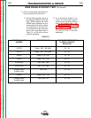
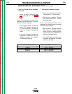
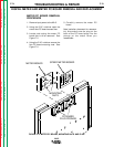
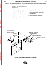
14. Test Speedmeter PC Board
Accuracy
• Use a test meter with at least 3-
1/2 digits and +/- 0.5% accuracy.
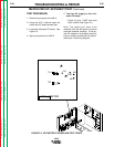
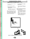
• Connect the + probe to lead #519
(Jumper lead) and the - probe to
lead #510P. Do not discon-
nect plug.
Note: The coating will have to be
removed from the test points to ensure
accurate meter readings.
• With the NA-5 speedmeter read-
ing SET values of STRIKE speed ,
adjust the strike wire speed con-
trol until the NA-5 speedmeter
matches the settings in the table
below.
• If the test meter does not match
the readings, the speedmeter PC
board may be faulty.
15. When the testing is complete close
and secure the access door.
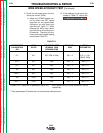
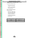
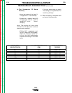
METER CIRCUIT ACCURACY TEST (Continued)
NA-5
SPEEDMETER NA-5 SET SPEED READING TEST VOLTMETER
CALIBRATION PIN (IPM) READING
21* 2.07* 6.00 +/- .06
57F 778 6.00 +/- .06
57 762 6.00 +/- .06
95 428 6.00 +/- .06
95S 456 6.00 +/- .06
142 289 6.00 +/- .06
142T 300 6.00 +/- .06
* For Hi-Speed NA-5 speedmeter (IPM X 1000)
Return to Section TOC Return to Section TOC Return to Section TOC Return to Section TOC
Return to Master TOC Return to Master TOC Return to Master TOC Return to Master TOC