


MECHANICAL
INSTALLATION
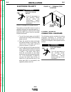
ELECTRIC SHOCK
can kill.
• Turn off input power to
the welding power source
using the disconnect
switch before working on
this equipment.
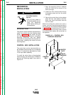
INTRODUCTION
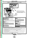
This section covers the basic requirements to
install the control box and welding head
shown in Figure A.1. This section will give
you mounting hole alignments, component
mounting clearances, and any special
instructions or precautions that must be fol-
lowed when installing the control box and
mounting head.
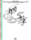
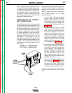
CONTROL BOX INSTALLATION
The control box can be mounted either on
the standard travel carriage or on a separate
fixture. It is electrically grounded by a lead
in the input cable assembly.
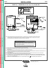
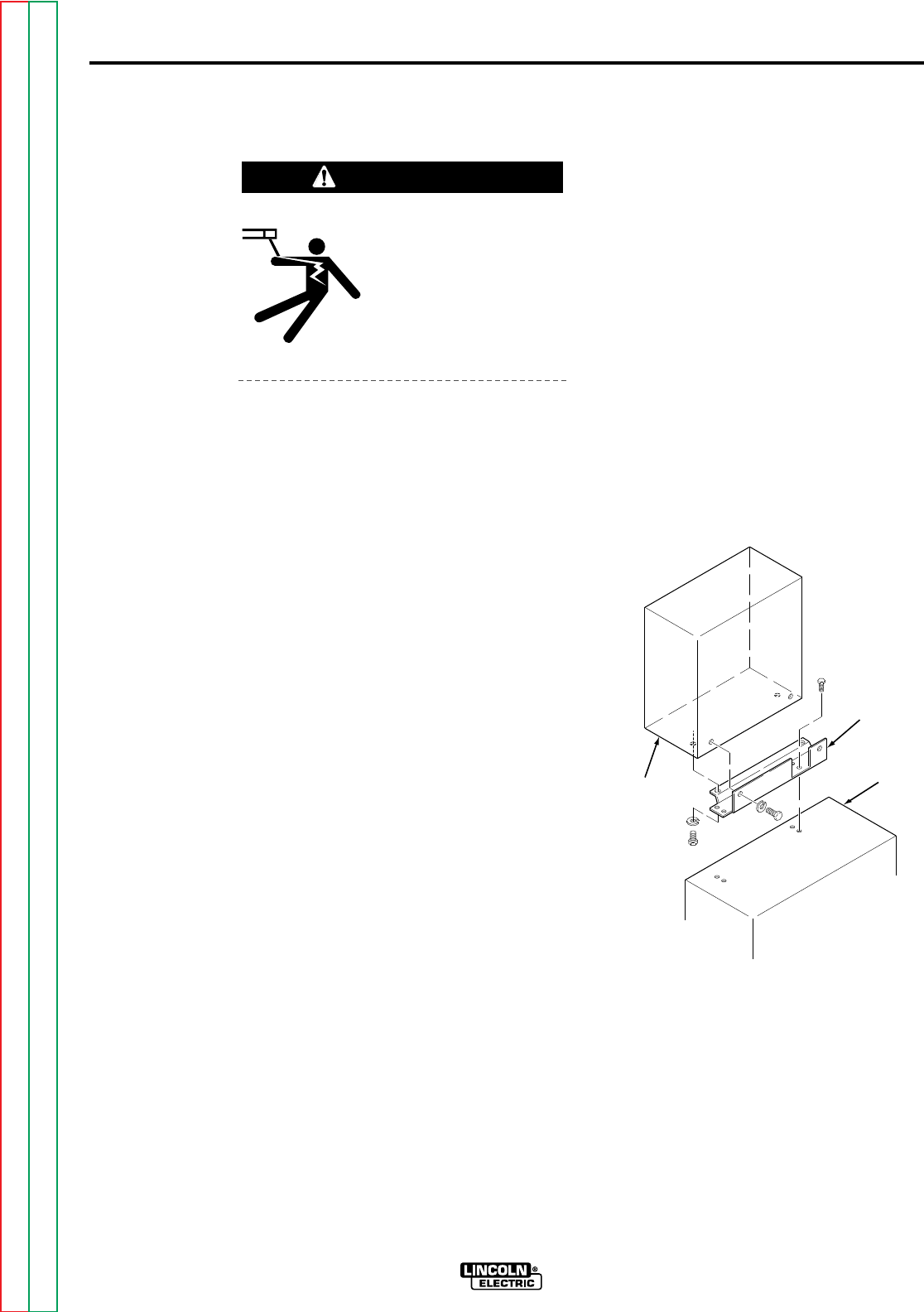
To install the control box on the standard
travel carriage, use mounting kit T14469 and
perform the following steps. Also refer to
Figure A.2.
1. Align the mounting holes in adapter
plate M-13945 to the holes in the
travel carriage.
2. Install four hex head screws through
the adapter plate and into the travel
carriage.
3. Secure the control box to the adapter
plate with four lock washers and four
bolts, two from the bottom and two
from the back.
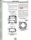
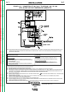
Before mounting the control box onto a
fixture, you must provide mounting holes in
the fixture per the measurements provided
in Figure A.3 or dimension print S16717.
When placing the mounting holes, ensure
the controls and meters are convenient to
the operator.
INSTALLATION
A-4
A-4
NA-5
WARNING
ADAPTER
PLATE
TRAVEL
CARRIAGE
CONTROL
BOX
FIGURE A.2 – CONTROL BOX
CARRIAGE MOUNTING.
Return to Section TOC Return to Section TOC Return to Section TOC Return to Section TOC
Return to Master TOC Return to Master TOC Return to Master TOC Return to Master TOC