


F-63
TROUBLESHOOTING & REPAIR
F-63
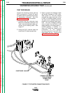
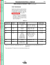
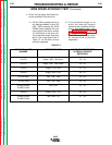
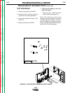
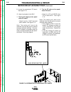
3. Check for the proper drive roll revo-
lutions per minute. (RPM)
A. Adjust the STRIKE speed con-
trol to obtain the SET speed
specified for the speedmeter
calibration pin and head ratio
specified per Table F.5 While
pressing the INCH down button
count the drive roll revolutions in
60 seconds. The drive roll revo-
lutions and actual speed reading
should match Table F.5
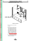
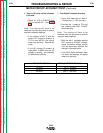
B. If the readings do not match the
number in Table F.5 refer to the
Meter Circuit Accuracy Test
.
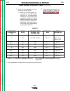
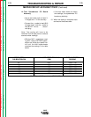
WIRE SPEED ACCURACY TEST (Continued)
NA-5
SPEEDMETER HEAD SET SPEEDMETER DRIVE ROLL ACTUAL
CALIBRATION RATIO READING (IPM) RPM SPEEDMETER
PIN READING (IPM)
21* 21/1 0.27 (IPM X 1000) 50 +/- 2 0.27 +/- 0.01
(IPM X 1000)
57F** 57/1 268 50 +/- 1 268 +/- 2
57** 57/1 262 50 +/- 1 262 +/- 2
95 95/1 249 50 +/- 1 249 +/- 2
95S*** 95/1 265 50 +/- 1 265 +/- 2
142 142/1 250 50 +/- 1 250 +/- 2
142T*** 142/1 260 50 +/- 1 260 +/- 2
TABLE F.5
* Present on HI -Speed NA-5 speedmeter board only. ** Early speedmeter pins were labeled 55F and 55,
respectively.
*** Early speedmeter PC boards did not include these calibration pins.
Return to Section TOC Return to Section TOC Return to Section TOC Return to Section TOC
Return to Master TOC Return to Master TOC Return to Master TOC Return to Master TOC