


INSTALLATION
A-8A-8
NA-5
ELECTRODE POLARITY
ELECTRIC SHOCK
can kill.
• Turn off input power to
the welding power
source using the
disconnect switch
before working on this
equipment.
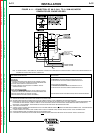
Polarity is changed at the power source.
The polarity of the NA-5 control circuit is
shipped connected for electrode positive. If
electrode negative is required, two leads
inside the NA-5 control must be reversed.
Proceed as follows:
1. Turn off the input power to the NA-5
control box by turning off the welding
power source.
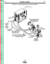
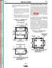
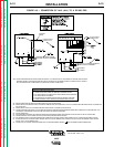
2. Open the control box door and locate
the terminal strips on the back of the
control box in the lower left-hand
corner as shown in Figure A.7.
3. On the right end of the lower terminal
strip, interchange the black and white
leads going to the terminals marked
(+) and (-). The black lead (#67)
must be connected to the same
polarity as the electrode welding lead;
i.e. if the electrode is positive,
connect the black lead to the (+)
terminal on the terminal strip. The
white lead (#21) is connected to the
opposite polarity terminal.
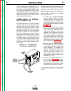
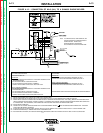
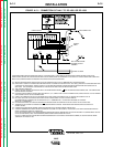
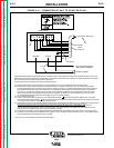
POWER SOURCE
CONNECTION DIAGRAMS
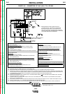
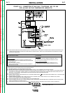
The following section contains the wiring
diagrams necessary to connect the
applicable power source to the control box.
If there is no diagram, refer to power source
manual.
ELECTRIC SHOCK
can kill.
• Turn off input power to
the welding power
source using the
disconnect switch
before working on this
equipment.
WARNING
TERMINAL
STRIPS
FIGURE A.7 – TERMINAL STRIP
LOCATION.
WARNING
Return to Section TOC Return to Section TOC Return to Section TOC Return to Section TOC
Return to Master TOC Return to Master TOC Return to Master TOC Return to Master TOC