


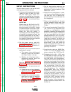
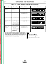
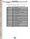
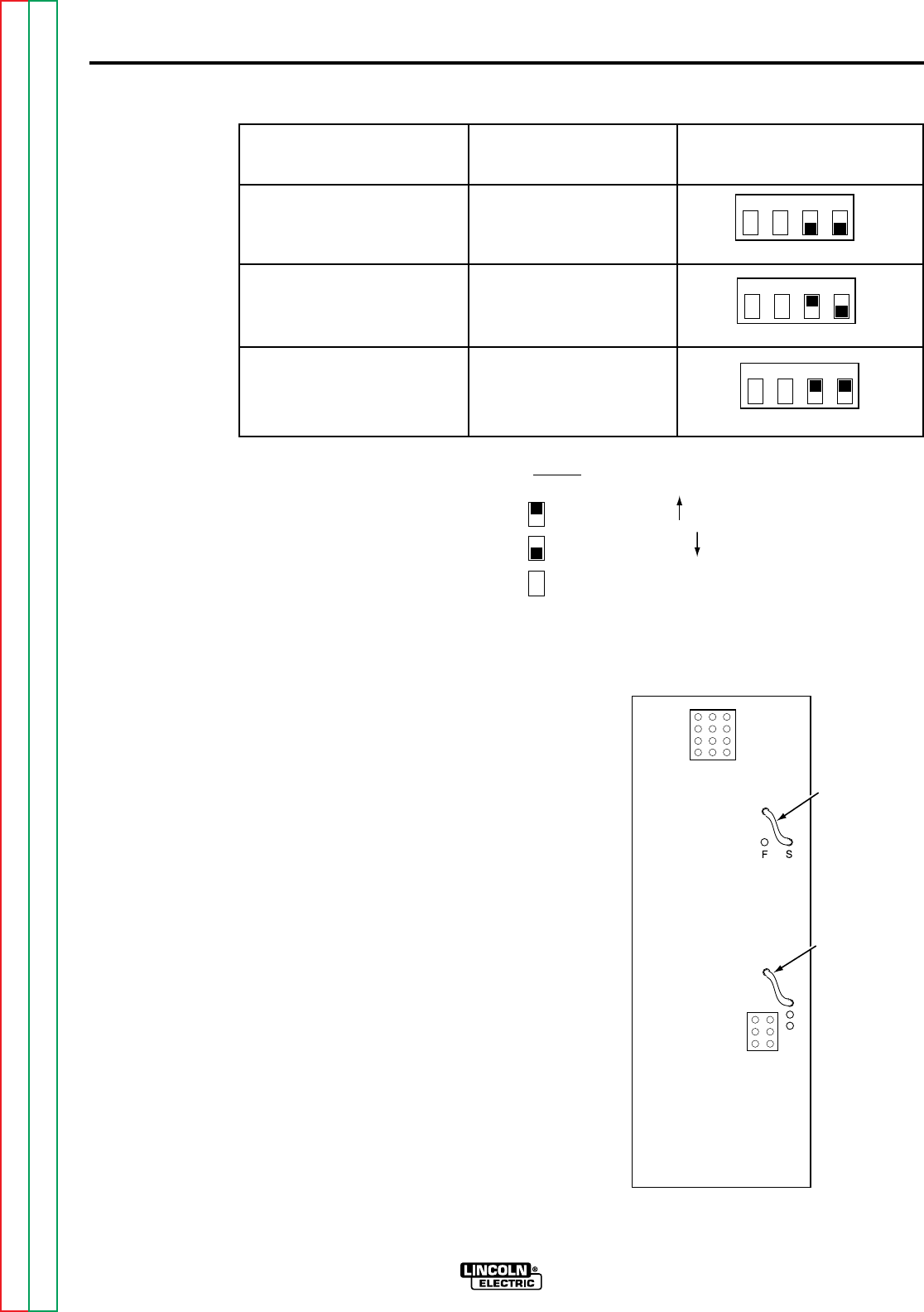
TABLE B.2 – STOPPING SEQUENCE SETTINGS.
When “Stop” Button
is Pressed Older Models Newer Models*
Feed motor stops and Lead #693 to Pin 3
electrode burns back with Lead #690 to Pin 4
contactor delay (standard)
Feed motor inches up and Lead #693 to Pin 1
electrode burns back with Lead #690 to Pin 4
contactor delay
Feed motor inches up and Lead #693 to Pin 1
contactor opens Lead #690 to Pin 2
(no burnback)
*NOTE:
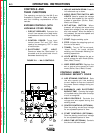
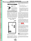
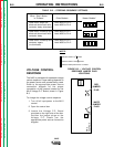
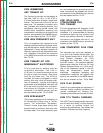
VOLTAGE CONTROL
RESPONSE
The NA-5 is provided with selectable voltage
control response. Proper setting depends on
the power source and process being used.
Refer to the appropriate power source
connection diagram for the proper
connection of the jumpers located on the
NA-5 Voltage P.C. Board, shown in Figure
B.3.
To change the voltage control response:
1. Turn off all input power to the NA-5
control.
2. Open the control box.
3. Locate the Voltage P.C. Board
mounted on the right side of the box.
Position the jumper plugs on the
Voltage P.C. Board per the
appropriate power source connection
diagram.
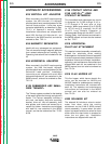
1234
Switch #2
1234
Switch #2
1234
Switch #2
OPERATING INSTRUCTIONS
B-9B-9
NA-5
Indicates switch in up position
Indicates switch in down position
Indicates switch position does not matter
NA-5
VOLTAGE
A
D
B
RED
JUMPER
PLUG
WHITE
JUMPER
PLUG
FIGURE B.3 – VOLTAGE CONTROL
RESPONSE JUMPER PLUG
LOCATIONS.
Return to Section TOC Return to Section TOC Return to Section TOC Return to Section TOC
Return to Master TOC Return to Master TOC Return to Master TOC Return to Master TOC