


E-5
THEORY OF OPERATION
E-5
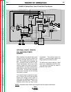
OPTIONAL START, CRATER
FILL AND WELD TIMER
BOARDS
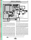
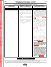
When installed, the optional start board
dictates to the procedure board the
starting wire feed speed and arc volt-
age. This condition can be operator set
for a predetermined period of time.
These parameters can be set either
higher or lower than those of the weld-
ing procedure to control penetration,
bead shape, or other factors at the start
of the weld. The start circuit becomes
active when the weld current sensing
reed switch is closed.
The crater fill board is used by the oper-
ator to adjust the finishing wire feed
speed and voltage either higher or
lower than the welding procedure for an
adjustable period of time. This circuit
becomes active when the "stop" switch
is pressed. This optional feature is
helpful in controlling bead shape and
filling craters at the end of a weld.
The weld timer permits setting of weld
time for an adjustable period of time.
This feature eliminates the need to
press the "stop" switch.
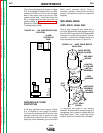
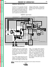
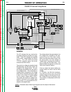
FIGURE E.3 Optional Start, Crater Fill and Weld Timer Boards
NA-5
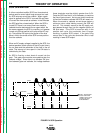
NOTE: Unshaded areas of block logic diagrams are the subject of discussion.
F1
A
R
M
A
T
U
R
E
F
I
E
L
D
V
O
L
T
A
G
E
V
O
L
T
A
G
E
T1 T2
OPTIONAL
START
BOARD
OPTIONAL
CRATER
BOARD
OPTIONAL
WELD
TIMER
BURNBACK
TIMER
VOLTAGE
BOARD
METER
BOARD
SPEED
VOLT
METER
BOARD
DIGITAL
METER
DIGITAL
METER
MOTOR
LOGIC
BOARD
CONTROL
BOARD
P
O
W
E
R
B
O
A
R
D
P
R
O
C
E
D
U
R
E
B
O
A
R
D
TACH
INCH
DOWN
SWITCH
STOP
SWITCH
START
SWITCH
WELD
CURRENT
REED SWITCH
CR
1
CR
2
CR
3
FLUX
RECEPTACLE
TRAVEL
RECEPTACLE
CONTACTOR CLOSURE (#2 AND #4)
REMOTE VOLTAGE CONTROL (A, B, C)
WORK SENSING (#21)
TACH FEEDBACK (MOTOR RPM)
DC SUPPLY VOLTAGE
10VDC REFERENCEVOLTAGE
DC VOLTAGE
S
I
G
N
A
L
INPUT
POWER
SWITCH
CIRCUIT
BREAKER
R1(2 OHMS)
MOTOR
G
A
T
E
S
I
G
N
A
L
S
CONTROL
CABLE
RECEPTACLE
TACH FEEDBACK (MOTOR RPM)
115VAC
36VAC (18+18VAC)
22VAC
1
V
A
C
0
D
C
S
U
P
P
L
Y
V
O
L
T
A
G
E
SIGNAL
A
R
C
V
O
L
T
A
G
E
S
H
U
T
D
O
W
N
A
N
D
INCH
UP
SWITCH
STRIKE/WELD PROCEDURE
ENABLE
FIELD
ARMATURE
F
E
E
D
E
N
A
B
L
E
DIRECTION
ARC VOLTS (SET & ACTUAL)
WIRE FEED SPEED (SET & ACTUAL)
E
L
E
C
T
R
ODE SENSING
(#67)
115
VAC
WELD
VOLTS SPEED
VOLTS SPEED
STRIKE
115VAC
#31
#32
1/2 AMP
F501
SET SPEED
SET VOLTAGE
START
TIMER
CRATER
TIMER
F2
Return to Section TOC Return to Section TOC Return to Section TOC Return to Section TOC
Return to Master TOC Return to Master TOC Return to Master TOC Return to Master TOC