


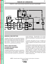

OUTPUT RECTIFICATION,
CONTROL, AND FEEDBACK
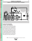
The three-phase AC output from the main transformer
secondary is rectified and controlled through the SCR/
diode bridge. Output current and voltage is sensed at
the shunt and output terminals. This feedback infor-
mation is processed in the control board. The control
board compares the commands from Arc Force
Control, the Dial Selector switch, and the Output
Control (or remote control) with the feedback informa-
tion and sends the appropriate gate firing signals to
the SCR/diode bridge. This creates a DC voltage at
the output of the bridge assembly. This DC voltage is
applied through the output choke to the output termi-
nals. The output choke, which is in series with the
negative output terminal, stores energy and provides
current filtering for the constant current welding arc.
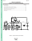
THEORY OF OPERATION
E-3 E-3
IDEALARC R3R
Return to Section TOC Return to Section TOC Return to Section TOC Return to Section TOC
Return to Master TOC Return to Master TOC Return to Master TOC Return to Master TOC
NOTE: Unshaded areas of Block Logic Diagram are the subject of discussion.
FIGURE E.3 – OUTPUT RECTIFICATION, CONTROL, AND FEEDBACK
CONTROL BOARD
OUTPUT
CONTROL
ARC FORCE
CONTROL
CONTROL
TRANSFORMER
POWER
SWITCH
R
E
C
O
N
N
E
C
T
INPUT
CONTACTOR
TRANSFORMER
MAIN
SCR DIODE
HYBRIDBRIDGE
/
SHUNT
OUTPUT
CHOKE
NEGATIVE
OUTPUT
TERMINAL
POSITIVE
OUTPUT
TERMINAL
G
A
T
E
S
I
G
N
A
L
S
FEEDBACK
F
E
E
D
B
A
C
K
THERMOSTATS
FAN
MOTOR
TERMINAL
STRIP
REMOTE
SWITCH
DIAL
SELECTOR
SWITCH
SNUBBER
BOARD
AMPHENOL
POLARITY
SWITCH
OPTIONAL
OPTIONAL
POCKET
AMPTROL
PC BOARD
OPTIONAL
POCKET
AMPTROL
TRANSFORMER