


Return to Section TOC Return to Section TOC Return to Section TOC Return to Section TOC
Return to Master TOC Return to Master TOC Return to Master TOC Return to Master TOC
TROUBLESHOOTING & REPAIR
F-6 F-6
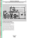
IDEALARC R3R
Observe Safety Guidelines TROUBLESHOOTING GUIDE
detailed in the beginning of this manual.
CAUTION
If for any reason you do not understand the test procedures or are unable to perform the test/repairs safely, con-
tact the Lincoln Electric Service Department for electrical troubleshooting assistance before you proceed. Call
216-383-2531 or 1-800-833-9353.
PROBLEMS
(SYMPTOMS)
POSSIBLE AREAS OF
MISADJUSTMENT(S)
RECOMMENDED
COURSE OF ACTION
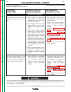
OUTPUT PROBLEMS
The machine has minimum (or very
low) welding output and no con-
trol.
1. Make certain the three-phase
input voltage is correct and
matches the rating plate and
the reconnect panel.
2. Make certain the Dial Control
Switch (SW3) is in the correct
position. (Not present on R3R
300).
3. If the remote control is being
used, set the Output Control
Switch (SW2) to the Machine or
Local position and control the
weld output with the machine
Output Control (R1). If the
problem is resolved, check the
remote control unit and associ-
ated cable leads. If the Pocket
Amptrol option is being used,
the Pocket Amptrol circuit may
be faulty.
4. Make sure the remote control
leads (#75, #76, #77) are not
grounded or shorted to the
positive or negative welding
output.
1. Check the Output Control (R1)
and associated wiring. See the
Wiring Diagram.
2. Check the Output Control
Switch (S2) and associated
wiring. See the Wiring
Diagram.
3. Perform the Main Transformer
Test.
4. Perform the SCR/Diode
Rectifier Bridge Test.
5. If the Pocket Amptrol is not
functioning properly, perform
the Pocket Amptrol Circuit
Test.
6. The control board may be
faulty. Replace.
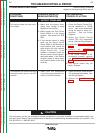
The input contactor operates - the
fan runs - the pilot light is on - but
the machine has no welding out-
put. The open circuit voltage is not
present at the output terminals.
1. Make certain the output control
switch (SW2) is in the Machine
or Local position. If the prob-
lem is resolved, check the
remote control and associated
circuitry. See the Wiring
Diagram.
1. Check for loose or faulty con-
nections on the heavy current
carrying leads between the out-
put terminals, the shunt, the
choke and the SRC/Diode
Bridge. See the Wiring
Diagram.
2. Perform the SCR/Diode
Rectifier Bridge Test.
3. Perform the Main Transformer
Test.
4. The control board may be
faulty. Replace.