


Return to Section TOC Return to Section TOC Return to Section TOC Return to Section TOC
Return to Master TOC Return to Master TOC Return to Master TOC Return to Master TOC
TROUBLESHOOTING & REPAIR
F-30 F-30
IDEALARC R3R
ACTIVE SCR TEST (continued)
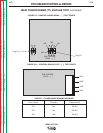
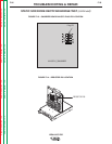
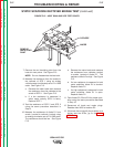
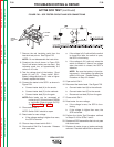
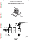
7. Remove the red insulating paint from the
heat sink test points. See Figure F.20.
NOTE: Do not disassemble the heat sinks.
8. Construct the circuit shown in Figure F.20.
One 6-volt lantern battery can be used., Set
voltmeter scale low, at approximately 0-5
volts or 0-10 volts.
9. Test the voltage level of the battery. Short
leads (A) and (C). Close switch SW-1.
Battery voltage should be 4.5 volts or higher.
If lower, replace the battery.
10. Connect the tester to the SCR 1 as shown in
Figure F.20.
a. Connect tester lead (A) to the anode.
b. Connect tester lead (C) to the cathode.
c. Connect tester lead (G) to the gate.
NOTE: Gate leads can be accessed at
molex plug P4 (Control board G2206)
or terminals (Control board G1575).
See Figures F.16 and F.17.
11. Close switch SW-1.
NOTE: Switch SW-2 should be open.
12. Read meter for zero voltage.
a. If the voltage reading is higher than zero,
the SCR is shorted.
13. Close or keep closed switch SW-1.
14. Close switch SW-2 for 2 seconds. Release
and read meter.
a. If the voltage is 3-6 volts while the switch
is closed and after the switch is open,
the SCR is functioning.
b. If the voltage is 3-6 volts only when the
switch is closed or if there is no voltage
when the switch is closed, the SCR is
defective.
NOTE: Be sure the battery is function-
ing properly. A low battery can affect the
results of the test. Repeat Battery Test
Procedure in Step 9 if needed.
15. Open switch SW-1.
16. Reconnect the tester leads. See Figure F.20.
a. Connect tester lead (A) to the cathode.
b. Connect tester lead (C) to the anode.
c. Disconnect test lead (G) from the gate.
17. Close switch SW-1.
18. Read meter for zero voltage.
a. If the voltage is zero, the SCR is func-
tioning.
b. If the voltage is higher than zero, the
SCR is shorted.
19. Perform the Active Test Procedure outlined
in Steps 10-18 for SCRs 2 and 3.
20. Replace all SCR assemblies that do not pass
the above tests.
21. Replace all molex plugs or leads previously
removed. Resolder lead #204 to resistor R3.
FIGURE F.20 – SCR TESTER CIRCUIT AND SCR CONNECTIONS
REMOVE
INSULATING
PAINT
CATHODE
ANODE