


Return to Section TOC Return to Section TOC Return to Section TOC Return to Section TOC
Return to Master TOC Return to Master TOC Return to Master TOC Return to Master TOC
TROUBLESHOOTING & REPAIR
F-5 F-5
IDEALARC R3R
TROUBLESHOOTING GUIDE Observe Safety Guidelines
detailed in the beginning of this manual.
CAUTION
If for any reason you do not understand the test procedures or are unable to perform the test/repairs safely, con-
tact the Lincoln Electric Service Department for electrical troubleshooting assistance before you proceed. Call
216-383-2531 or 1-800-833-9353.
PROBLEMS
(SYMPTOMS)
POSSIBLE AREAS OF
MISADJUSTMENT(S)
RECOMMENDED
COURSE OF ACTION
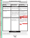
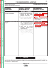
OUTPUT PROBLEMS
The machine is dead – no output –
no fan. The input contactor does
not operate. The amber thermal
protection light is on. The pilot
light is on.
1. If the amber thermal protection
light is on, the primary or sec-
ondary thermostat is open.
Allow the machine to cool.
Check the fan motor for proper
operation. Make sure all case
openings are free for proper cir-
culation of air. Operate the
machine at rated current and
duty cycle.
1. Check the leads and connec-
tions between the thermostats,
the input contactor (1CR) and
the power switch (SW1). See
the Wiring Diagram.
2. One of the (normally closed)
thermostats may be faulty.
The input contactor (CR1) chatters. 1. Make certain the three-phase
input voltage matches the rat-
ing plate and the reconnect
panel.
1. Perform the Input Contactor
Test.
The machine has high welding out-
put and no control.
1. If the remote control is being
used, set the output control
switch (SW2) to the Machine or
Local position and control the
weld output with the machine
Output Control (R1). If the
problem is resolved, check the
remote control unit and associ-
ated cable leads. If the Pocket
Amptrol option is being used,
the Pocket Amptrol circuit may
be faulty.
1. Check the Output Control
Switch (SW2) and the Dial
Selector Switch (SW3) and
associated wiring. See the
Wiring Diagram.
2. Check the feedback leads
#205, #206, #204 and #225 for
loose or faulty connections.
3. Perform the SCR/Diode
Rectifier Bridge Test.
4. If the Pocket Amptrol is not
functioning properly, perform
the Pocket Amptrol Circuit
Test.
5. The control board may be
faulty. Replace.