


Return to Section TOC Return to Section TOC Return to Section TOC Return to Section TOC
Return to Master TOC Return to Master TOC Return to Master TOC Return to Master TOC
TROUBLESHOOTING & REPAIR
F-25 F-25
IDEALARC R3R
STATIC SCR/DIODE RECTIFIER BRIDGE TEST (continued)
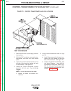
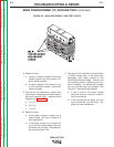
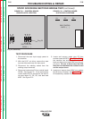
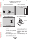
FIGURE F.11 – CONTROL BOARD
G2206 PLUG P4 LOCATION
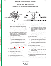
TEST PROCEDURE
1. Disconnect the main input supply power to
the machine.
2. With the 5/16” nut driver, remove the case
top and sides and lower the front panel.
3. Disconnect the welding cables from the
welding output terminals.
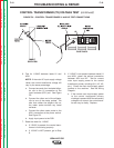
4. Disconnect molex plug P4 from control board
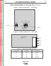
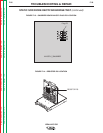
G2206. See Figure F.11. If the machine has
control board G1575, disconnect the individ-
ual gate leads G1, G2, G3, and also lead
#204. See Figure F.12.
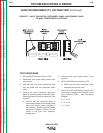
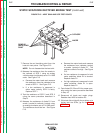
5. Locate and remove molex plug P5 from
snubber board M15370. See Figure F.13. If
the machine has snubber board M14215,
label and disconnect Lead #204 from the out-
put shunt. Be sure to disconnect the #204
lead that runs between the snubber board
and the output shunt.
6. Locate and remove lead #204 from resistor
R3 (40 ohms, 50 watts). See Figure F.14. On
R3 reassembly, resolder this lead.
R3R CONTROL
G2206 - [ ]
Plug P3
Plug P4 (Removed)
FIGURE F.12 – CONTROL BOARD
G1575 LEAD LOCATIONS
R3R CONTROL
G1575 - [ ]
G1 G2 G3