


Return to Section TOC Return to Section TOC Return to Section TOC Return to Section TOC
Return to Master TOC Return to Master TOC Return to Master TOC Return to Master TOC
TROUBLESHOOTING & REPAIR
F-14 F-14
IDEALARC R3R
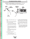
INPUT CONTACTOR TEST (continued)
TEST PROCEDURE
1. Disconnect the main input supply power to
the machine.
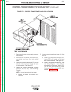
2. With the 5/16” nutdriver, remove the case
top and the reconnect panel cover.
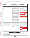
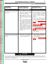
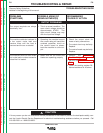
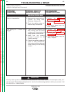
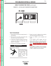
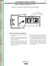
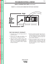
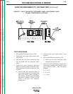
3. Locate the two leads connected to the input
contactor coil, #233A and #232A. See
Figure F.3.
4. Connect a DC voltmeter to the leads.
Electric Shock can kill.
• With the input power
on, there are high volt-
ages inside the
machine. Do not reach
into the machine or
touch any internal part
of the machine while the
power is on.
5. Apply the correct voltage to the machine
and turn the power switch (S1) ON.
6. Check for approximately 120VDC at the
contactor coil leads. If the 120VDC IS pre-
sent at the contactor coil, the input contac-
tor should activate. If it does not, the input
contactor may be faulty. Check or replace.
If the 120VDC is NOT present, check for
120VAC at leads #233 and #232 at diode
bridge D8. See the Wiring Diagram. If the
AC voltage IS present but the DC voltage is
low or not present, the diode bridge may
be faulty. Check or replace.
If the 120VAC is NOT present at leads #232
and #233, with the power switch (S1) on,
check the power switch, thermostats, and
associated circuitry. See the Wiring
Diagram.
WARNING
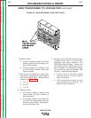
FIGURE F.3 – DC COIL INPUT CONTACTOR CONNECTIONS
A
A