


Return to Section TOC Return to Section TOC Return to Section TOC Return to Section TOC
Return to Master TOC Return to Master TOC Return to Master TOC Return to Master TOC
TROUBLESHOOTING & REPAIR
F-36 F-36
IDEALARC R3R
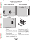
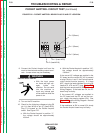
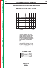
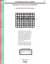
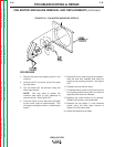
This is the typical DC voltage wave-
form generated from a properly oper-
ating machine. Note that each verti-
cal division represents 20 volts and
that each horizontal division repre-
sents 5 milliseconds in time. The
machine was loaded with a resis-
tance grid bank. The meter reads
500 amps at 40VDC.
Note: Scope probes connected at
machine output terminals: (+) probe
to positive terminal, (-) probe to neg-
ative terminal. (R3R 500 machine)
SCOPE SETTINGS
Volts/Div.....................20V/Div.
Horizontal Sweep.....5 ms/Div.
Coupling ............................DC
Trigger .........................Internal
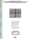
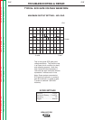
TYPICAL OUTPUT VOLTAGE WAVEFORM – MACHINE LOADED
0 volts
5 ms
20 volts