


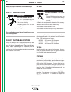
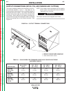
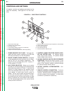
The output (welding) cables are connected to the out-
put terminals marked “+” and “-”. See Table A.1 for
recommended cable sizes for the combined lengths of
electrode and work cables. The output terminals are
located at the lower right and lower left corners of the
front panel. Strain relief for the cables is provided by
routing them through the rectangular holes in the base
before connecting them to the output terminals. See
Figure A.4.
NOTE: If the welder comes equipped with the polarity
switch option, the output terminals are labeled
“electrode” and “to work.”
The output terminals are energized at all times.
INSTALLATION
A-9 A-9
IDEALARC R3R
Return to Section TOC Return to Section TOC Return to Section TOC Return to Section TOC
Return to Master TOC Return to Master TOC Return to Master TOC Return to Master TOC
FIGURE A.4 - OUTPUT TERMINAL CONNECTIONS
1
2
3
1. NEGATIVE (-) WELDING CABLE CONNECTION
2. POSITIVE (+) WELDING CABLE CONNECTION
3. CABLE STRAIN RELIEF HOLES
OUTPUT CONNECTIONS (STICK, TIG, AIR/CARBON ARC CUTTING)
WARNING
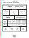
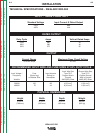
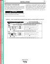
TABLE A.1 - CABLE SIZES FOR COMBINED LENGTHS OF COPPER ELECTRODE
AND WORK CABLES
Up to 100 ft 100 - 150 ft 150 - 200 ft 200 - 250 ft
Machine Size (30 m) (30 - 46 m) (46 - 61 m) (67 - 76 m)
300 Amp 1/0 1/0 2/0 3/0
(60% Duty 54 mm
2
54 mm
2
68 mm
2
86 mm
2
Cycle)
400 Amp 2/0 2/0 3/0 4/0
(60% Duty 68 mm
2
68 mm
2
86 mm
2
108 mm
2
Cycle)
500 Amp 2/0 3/0 3/0 4/0
(60% Duty 68 mm
2
86 mm
2
86 mm
2
108 mm
2
Cycle)