


Return to Section TOC Return to Section TOC Return to Section TOC Return to Section TOC
Return to Master TOC Return to Master TOC Return to Master TOC Return to Master TOC
TROUBLESHOOTING & REPAIR
F-44 F-44
IDEALARC R3R
SCR/DIODE RECTIFICER ASSEMBLY
REMOVAL AND REPLACEMENT (continued)
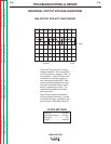
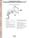
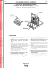
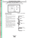
FIGURE F.27 – SCR/DIODE ASSEMBLY DETAILS
GLASTIC
STIFFENERS
CHOKE
SECONDARY
LEADS
MOUNTING
BRACKETS
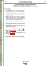
PROCEDURE
1. Remove the main input supply power to the
machine.
2. With the 5/16” nut driver, remove the case
top and sides. Lower the front control
panel.
3. Using the 5/16” wrench, remove the six
screws mounting the front assembly to the
machine’s base. Carefully “inch” the front
forward to make room for the removal of the
SCR/diode bridge assembly.
4. Remove the two screws holding the air
deflector (R3R 500 only) to the front panel.
Remove the air deflector.
5. Remove the glastic stiffeners (one on each
side-left and right). See Figure F.27.
6. Remove the choke from the left side of the
negative heat sink plate. See Figure F.27.
7. Remove the two #220 leads from the right
side of the negative heat sink plate.
8. Remove the positive lead and shunt from the
positive heat sink plate. See Figure F.27.
9. Remove the gate leads from the control
board (either plug J4 or individual gate
leads).
10. Remove the three heavy aluminum sec-
ondary leads and snubber leads from the
SCR finned heat sinks. (Note lead placement
for reassembly.)
11. Remove the four nuts and associated wash-
ers that hold the SCR/diode assembly to the
mounting brackets.
12. Carefully lift and remove the SCR/diode heat
sink assembly from the machine. Clear any
necessary leads that might hinder removal.