


Return to Section TOC Return to Section TOC Return to Section TOC Return to Section TOC
Return to Master TOC Return to Master TOC Return to Master TOC Return to Master TOC
TROUBLESHOOTING & REPAIR
F-33 F-33
IDEALARC R3R
POCKET AMPTROL CIRCUIT TEST (continued)
8. Connect the Pocket Amptrol unit from the
work to the electrode welding output termi-
nals. Jumper wires may be necessary.
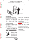
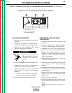
Electric Shock can kill.
• With the input power
on, there are high volt-
ages inside the
machine. Do not reach
into the machine or
touch any internal part
of the machine while the
power is on.
9. Turn on the R3 machine.
10. Check for the following voltages at plug P6
pin 1(+) (lead #218) to pin 2(–) (lead #219).
Plug 6 is located on the Pocket Amptrol
board. See Figure F.22.
a. With the Pocket Amptrol in position “1”,
the voltage should be approximately
40.8mV.
b. With the Pocket Amptrol in position “10”,
the voltage should be approximately
138.9mV.
If the correct AC voltages are applied to the
PC board and the correct DC mV is sensed
at plug P6 pins 1 and 2, the Pocket Amptrol
circuit should function properly. If it does
NOT, check the leads between the plug P6
(leads #75, #76 and #77) (see Figure F.24)
and the local remote switch (SW2). See the
Wiring Diagram. If the leads are OK, the PC
board may be faulty.
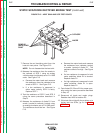
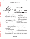
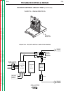
If the correct AC voltages are applied to
the PC board and the DC mV are not cor-
rect, check the sensing resistor (R4). See
Figure F.23 and the Wiring Diagram. Normal
resistance is 0.4 ohms.
If the resistance at R4 is normal (0.4 ohms)
the Pocket Amptrol board may be faulty.
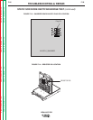
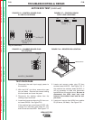
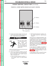
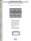
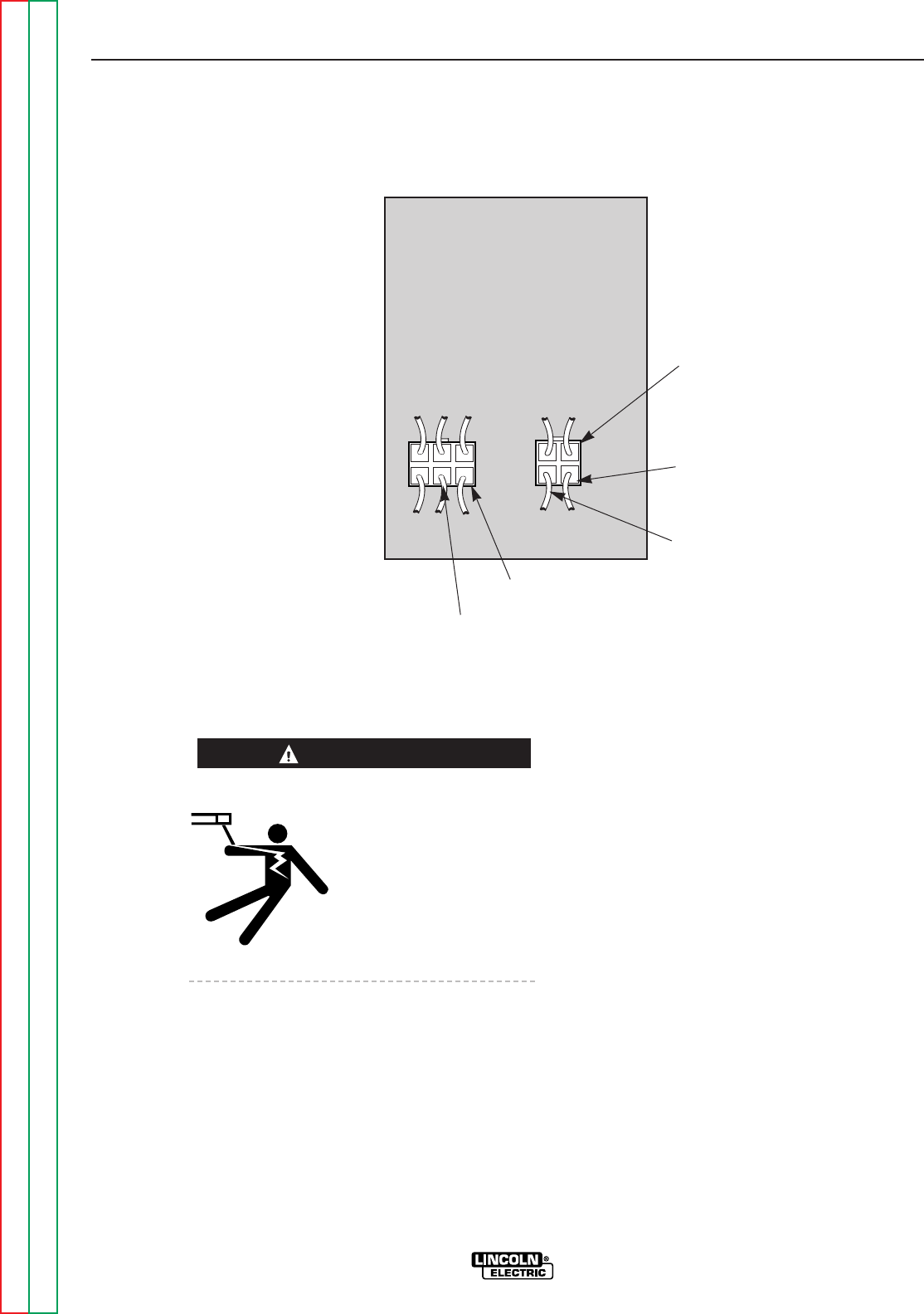
FIGURE F.22 – POCKET AMPTROL BOARD PLUG P6 AND P7 LOCATION
P6
Pin 3 (Green)
Pin 1 (Green)
Pin 2 (Yellow)
Pin 1 (Lead #218)
Pin 2 (Lead #219)
P7
WARNING