


Return to Section TOC Return to Section TOC Return to Section TOC Return to Section TOC
Return to Master TOC Return to Master TOC Return to Master TOC Return to Master TOC
TROUBLESHOOTING & REPAIR
F-32 F-32
IDEALARC R3R
POCKET AMPTROL CIRCUIT TEST (continued)
TEST PROCEDURE
1. Remove input power to the R3R machine.
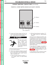
2. Using the ohmmeter, check the resistance
from one probe to the other probe at the
Pocket Amptrol. Normal resistance is 700
ohms when the dial is at the “1” position.
When the dial is rotated toward the “10” posi-
tion, the resistance from probe to probe
should decrease to approximately 200 ohms.
If the measured resistance is not correct, the
Pocket Amptrol may be faulty.
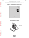
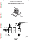
3. Using the 5/16” nut driver, lower the front
panel and locate the Pocket Amptrol trans-
former T3 inside the control box compart-
ment. See Figure F.21.
NOTE: If the machine is equipped with a polari-
ty switch, the switch handle will have to
be removed using a 1/8” Allen type
wrench.
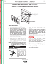
Electric Shock can kill.
• With the input power on,
there are high voltages
inside the machine. Do
not reach into the
machine or touch any
internal part of the
machine while the power
is on.
4. Apply the correct input power to the
machine.
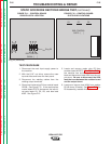
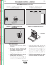
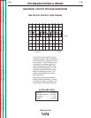
5. Check the T3 primary voltage at leads #201A
to 203A. See Figure F.21. Normal voltage is
approximately 120VAC. If the primary volt-
age is missing or low, check the leads and
associated connections.
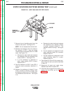
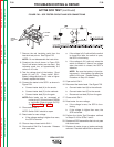
6. Check the T3 secondary voltages at plug P7
located on the Pocket Amptrol board. See
Figure F.22.
Check pin 1 (green lead) to pin 2 (yellow
lead). Normal is approximately 12VAC.
Check pin 3 (green lead) to pin 2 (yellow
lead). Normal is approximately 12VAC.
If the correct primary voltage is applied to the
T3 transformer and either of the secondary
voltages are missing or low, the T3 trans-
former may be faulty.
7. Turn off the R3R machine.
FIGURE F.21 – T3 TRANSFORMER AND LEADS (POCKET AMPTROL)
POCKET
AMTROL
TRANSFORMER
T3
WARNING