


TROUBLESHOOTING & REPAIR
F-63 F-63
PRO-CUT 55
Return to Section TOC Return to Section TOC Return to Section TOC Return to Section TOC
Return to Master TOC Return to Master TOC Return to Master TOC Return to Master TOC
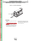
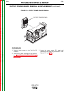
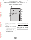
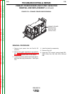
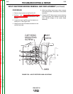
FIGURE F.23 – PRIMARY POWER BOARD REMOVAL
PRIMARY POWER
BOARD WITH
INPUT FILTER
CAPACITORS
PRIMARY POWER BOARD AND FILTER CAPACITOR
REMOVAL AND REPLACEMENT (continued)
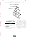
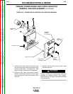
REMOVAL PROCEDURE
1. Remove input power from the Pro-Cut 55
machine.
2. Remove the case wraparound and perform
the Input Filter Capacitor Discharge
Procedure detailed earlier in this section.
3. Locate the primary power board and associ-
ated lead and plug connections. See Figure
F.23.
4. Label the leads for reassembly.
5. Remove Plug J10.
6. Using the 7/16” wrench, remove leads 201,
202A, 203A, 204, 205, 206, 207A, 208 and
209.