


Return to Section TOC Return to Section TOC Return to Section TOC Return to Section TOC
Return to Master TOC Return to Master TOC Return to Master TOC Return to Master TOC
TROUBLESHOOTING & REPAIR
F-21 F-21
PRO-CUT 55
PRIMARY POWER BOARD RESISTANCE TEST AND
CAPACITOR VOLTAGE TEST (continued)
CAPACITOR VOLTAGE TEST
This test will help the technician to determine if
the input filter capacitors are being charged
equally to the correct voltage levels.
NOTE: This test should only be conducted with
the Pro-Cut 55 connected for 400 VAC and
above, and with the appropriate input voltage
applied.
TEST PROCEDURE
1. Remove main input power to the Pro-Cut
55.
2. Perform the Input Filter Capacitor
Discharge Procedure detailed earlier in
this section.
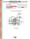
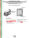
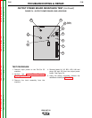
3. Locate and familiarize yourself with the
capacitor test locations on the primary
power board. See Figure F.3.
4. The following tests will be performed with
the input power applied to the Pro-Cut 55.
BE CAREFUL. ALWAYS REMOVE THE
INPUT POWER AND PERFORM THE
INPUT FILTER CAPACITOR DISCHARGE
PROCEDURE BEFORE TOUCHING ANY
MACHINE COMPONENT.
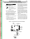
ELECTRIC SHOCK can kill.
• Have an electrician install and
service this equipment.
• Turn the input power off at the
fuse box before working on
equipment.
• Do not touch electrically hot parts.
5. Apply the correct input power
†
and turn ON
the Pro-Cut 55.
†
NOTE: This test should only be conducted
with the Pro-Cut 55 reconnect switch
and “A” jumper configured for 400
VAC and above.
WARNING