


TROUBLESHOOTING & REPAIR
F-41 F-41
PRO-CUT 55
Return to Section TOC Return to Section TOC Return to Section TOC Return to Section TOC
Return to Master TOC Return to Master TOC Return to Master TOC Return to Master TOC
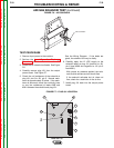
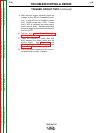
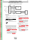
TRIGGER CIRCUIT TEST (continued)
G3326 PRO-CUT 55 OUTPUT
LED1
C13
+
LED2
D25
J32
J30
J31
LED4
LED3
LED5
LEAD#4
LEAD#2
LEAD#344
LEAD#312
G3326-2,3
LED1
LED2
LED4
LED3
LED5
LED6
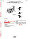
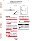
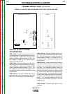
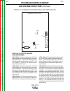
FIGURE F.10 - OUTPUT BOARD TRIGGER CIRCUIT TEST POINTS AND LEDS
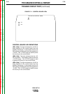
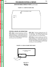
PRO-CUT 55 OUTPUT BOARD
LED DEFINITIONS
LED1: (Red) This light indicates that 24 VAC is
being supplied to the output board from the aux-
iliary transformer. It also shows that the 24 VAC
is being rectified to approximately 28 VDC. This
DC voltage is used for the "parts-in-place"
check for the torch circuit.
LED2: (Red) This light indicates that 12 VAC is
being supplied to the output board from the aux-
iliary transformer. It also shows that the 12 VAC
is being rectified to approximately 17 VDC. This
DC voltage is used to power the trigger circuit
and solenoid driver circuits incorporated on the
output board.
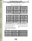
LED3: (Green) This light indicates that the air
solenoid driver circuit is functioning. When this
LED is lit, the air solenoid should be activated.
LED4: (Green) This light indicates that the trig-
ger circuit on the output board has been activat-
ed. This LED should be lit when the torch or
remote trigger is closed. This trigger circuit, on
the output board, then sends a signal to the
control board.
LED5: (Green) This light indicates that the elec-
trode solenoid driver circuit is functioning. When
this light is lit, the electrode solenoid should be
activated. The electrode solenoid should be
energized during gas (air) pre-flow time. During
pilot and cutting arc periods, the LED should be
off. When the arc goes out, the machine enters
the post-flow state. Two seconds after the start
of post-flow the electrode solenoid is activated a
few times. The LED should blink to indicate this
activity. The electrode solenoid will then be
energized for the duration of post-flow. (The LED
should be on.)
LED6: (Green) Indicates gate drive for pilot
transistor.