


7. If the correct test voltages are present, the
auxiliary transformer is good.
8. If any of the voltages are missing or very low
with the proper primary voltage applied, the
auxiliary transformer may be faulty.
9. If the auxiliary transformer tests good but it
does not function when connected to the
Pro-Cut 55, check the harness wiring to the
auxiliary transformer. See the Wiring
Diagram.
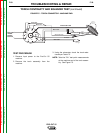
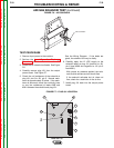
10. When finished with the test, replace plugs
21 and 22 and the case wraparound.
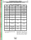
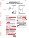
NOTE: There should not be continuity between
the isolated windings. With the input
power removed from the transformer,
check the windings using the table
below.
TROUBLESHOOTING & REPAIR
F-36 F-36
PRO-CUT 55
Return to Section TOC Return to Section TOC Return to Section TOC Return to Section TOC
Return to Master TOC Return to Master TOC Return to Master TOC Return to Master TOC
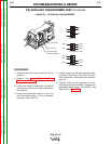
(T2) AUXILIARY TRANSFORMER TEST (continued)
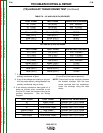
TEST POINT TEST POINT EXPECTED VOLTAGE
H1 (1J22) H2 (4J22) 200 - 208VAC
H1 (1J22) H4 (3J22) 380 - 415VAC
H1 (1J22) H5 (6J22) 440 - 460VAC
Brown (8J21) Brown (3J21) 12VAC
Red (2J21) Red (6J21) 24VAC
Blue (9J21) White (5J21) 18VAC
Blue (4J21) White (5J21) 18VAC
TABLE F.6 - J21 AND J22 (6 Pin) VOLTAGES
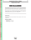
TEST POINT TEST POINT EXPECTED VOLTAGE
H1 (1J22) H2 (5J22) 200 - 208VAC
H1 (1J22) H4 (7J22) 380 - 415VAC
H1 (1J22) H5 (8J22) 440 - 460VAC
H1 (1J22) H6 (4J22) 560 - 600VAC
Brown (8J21) Brown (3J21) 12VAC
Red (2J21) Red (6J21) 24VAC
Blue (9J21) White (5J21) 18VAC
Blue (4J21) White (5J21) 18VAC
J21 AND J22 (8 Pin) VOLTAGES
TEST POINT TEST POINT EXPECTED RESISTANCE
H1 Brown Lead Greater than 100 K ohms
H1 Red Lead Greater than 100 K ohms
H1 Blue/White Leads Greater than 100 K ohms
Brown Leads Red Leads Greater than 100 K ohms
Brown Leads Blue/White Leads Greater than 100 K ohms
Red Leads Blue/White Leads Greater than 100 K ohms