


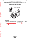
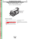
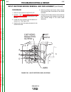


CAPACITOR REMOVAL
1. Using the 3/8” wrench, remove the four
screws holding the heat sink assembly to the
upper and bottom sections of the machine.
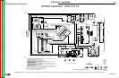
See Figure F.24.
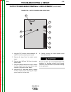
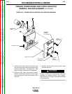
2. Remove the gas hose restraints from the bot-
tom of the heat sink assembly.
3. Remove the two thermostat leads from the
thermostat, which is located next to the
upper capacitor.
4. Carefully remove the heat sink and capacitor
assembly. Clear any necessary leads.
5. Remove the faulty capacitors by using the
slot head screw driver to loosen the clamps.
Take note of capacitor position in the clamp.
Observe polarity markings and terminal
position.
CAPACITOR REPLACEMENT AND
P.C. BOARD REPLACEMENT
1. Replace the capacitors by positioning them
in the clamps. Do not tighten the clamps.
They must be loose when the P.C. board is
assembled to the capacitors.
2. Apply a thin coating of Penetrox A-13
Electrical Joint Compound to the mating sur-
faces of the P.C. board and the heat sink and
capacitor terminals.
3. Mount the P.C. board to the heat sink and
capacitor assembly. Make sure the capacitor
terminals line up with the holes in the P.C.
board and with the correct capacitor polari-
ties.
4. Assemble the four socket head screws and
pre-torque them to 25 inch-pounds.
5. Make certain the capacitors are lined up
correctly so that when the capacitor bolts
are assembled through the P.C. board, there
will NOT be any distortion to the P.C. board.
6. Finish tightening the four screws to 40-48
inch-pounds.
7. Assemble the two slot head screws with
their appropriate insulators.
8. Tighten the capacitor clamps.
9. Place the assembly into the machine and
connect the two thermostat leads previous-
ly removed.
10. Secure the assembly to the upper and bot-
tom sections of the unit using the 3/8”
wrench and the four screws previously
removed.
11. Connect the J10 plug.
12. Connect leads 201, 204, 205, 208 and 209
previously removed.
13. Connect leads 202A, 207A, 206, and 203A
to the capacitor terminals. Torque to 50-60
inch-pounds.
14. Replace the gas hose restraints previously
removed.
15. Clear and reposition any leads that may be
disturbed.
16. Replace the case wraparound cover.
TROUBLESHOOTING & REPAIR
F-65 F-65
PRO-CUT 55
Return to Section TOC Return to Section TOC Return to Section TOC Return to Section TOC
Return to Master TOC Return to Master TOC Return to Master TOC Return to Master TOC
PRIMARY POWER BOARD AND FILTER CAPACITOR
REMOVAL AND REPLACEMENT (continued)