


"'( (#"
*(
Keeping these contributing factors in mind, installing
equipment per the following instructions should mini-
mize problems.
1. Keep the welder power supply lines as short as
possible and enclose as much of them as possible
in rigid metallic conduit or equivalent shielding for a
distance of 50ft. (15.2m). Both ends of the conduit
should be connected to a driven ground and the
entire length should be continuous.
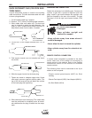
2. Keep the work and electrode leads as short as pos-
sible and as close together as possible. Lengths
should not exceed 25ft. (7.6m). Tape the leads
together when practical.
3. Be sure the torch and work cable rubber coverings
are free of cuts and cracks that allow high frequen-
cy leakage. Cables with high natural rubber con-
tent, such as Lincoln Stable-Arc
®
better resist high
frequency leakage than neoprene and other syn-
thetic rubber insulated cables.
4. Keep the torch in good repair and all connections
tight to reduce high frequency leakage.
5. The work terminal must be connected to a ground
within ten feet of the welder, using one of the follow-
ing methods.
a) A metal underground water pipe in direct con-
tact with the earth for ten feet or more.
b) A 3/4” (19mm) galvanized pipe or a 5/8”
(16mm) solid galvanized iron, steel or copper
rod driven at least eight feet into the ground.
The ground should be securely made and the
grounding cable should be as short as possible
using cable of the same size as the work cable, or
larger. Grounding to the building frame electrical
conduit or a long pipe system can result in re-radi-
ation, effectively making these members radiating
antennas.
6. Keep all panels securely in place.
7. All electrical conductors within 50 ft (15.2m) of the
welder should be enclosed in grounded, rigid metal-
lic conduit or equivalent shielding. Flexible metallic
conduit is generally not suitable.
8. When the welder is enclosed in a metal building,
several earth driven electrical grounds connected
(as in 5 (b) above) around the periphery of the
building are recommended.
Failure to observe these recommended installation
procedures can cause radio or TV interference prob-
lems.
"$)(#""(#"'
(&'#20=:8;;
M0E40@D0;858434;42CA8280=8=BC0;;
0=3B4AE824C78B4@D8?<4=C
M 8B2>==42C8=?DC?>F4A1HA4<>E8=6
?;D65A><A424?C02;4145>A4F>A:8=6
8=B834*(;;>F<0278=4C>B8C5>A
<8=DC4B
<8=8<D<C>0;;>FC74?>F4A20?028C>AB
C>38B270A64145>A4F>A:8=68=B834C78B4@D8?
<4=C
M>=>CC>D274;42CA820;;H7>C?0ACB
-----------------------------------------------------------------------
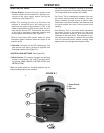
&#)"#""(#"
The frame of the welder must be
grounded. A ground terminal marked
with the symbol is located on the under
panel for this purpose. See your local
and national electrical codes for proper
grounding methods.
(746A>D=38=68BBD??;8438=C748=?DC2>A38C8B
8<?>AC0=CC70CC74'D??;H&424?C02;4A>D=32>=
=42C8>=8B2>==42C43
-----------------------------------------------------------------------
(78B8=BC0;;0C8>=B7>D;314?4A5>A<431H0@D0;8
58434;42CA8280=C>4=BDA42>AA42C2>==42C8>=B>5
C74;403BC>C74?;D6B?034B
• (744;42CA820;BHBC4<<DBC14<0341HB:8;;43
C427=8280=BF8C7C74B?428582?A>54BB8>=0;0=3
C427=820;@D0;85820C8>=B0=38=2><?;80=24F8C7
C74A46D;0C8>=B8=5>A248=C742>D=CAHF74A4C74
4@D8?<4=C8B8=BC0;;43
• (74F4;38=6?>F4AB>DA24BD??;H201;48B?A>
E8343F8C706A44=>AH4;;>F6A44=F8A4C70C<DBC
+-'1440AC743(78B6A44=>AH4;;>F6A44=
F8A4<DBC"*&14DB43F8C7>C74AE>;C064
2>=3D2C>AB
M;=BC0;;>=;H?;D6BC70C0A42>AA4B?>=38=6C>B054
CHA46D;0C8>=B
------------------------------------------------------------------------
+&""
)(#"
+&""