


E8
E8
( ##"("('
Page
=BC0;;0C8>='42C8>=
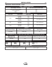
Technical Specifications .......................................................................................................A-1
Select Suitable Location.......................................................................................................A-2
Stacking................................................................................................................................A-2
Tilting....................................................................................................................................A-2
Machine Grounding and High Frequency Interference Protection .......................................A-2
Input Connections ................................................................................................................A-3
Ground Connection........................................................................................................A-3,A-4
ARFU (Auto-Restore Fuse)....................................................................................A-4
Output Connections..............................................................................................................A-5
Output and Gas Connection for Tig Welding........................................................................A-5
Output Connection for Stick Welding....................................................................................A-5
Work Cable Connection........................................................................................................A-5
Quick Disconnect Plug..................................................................................................A-6
Shielding Gas Connection.............................................................................................A-6
Remote Control Connection..........................................................................................A-6
________________________________________________________________________________
#?4A0C8>='42C8>=
Safety Instructions................................................................................................................B-1
General Description..............................................................................................................B-1
Welding Capability................................................................................................................B-1
Limitations ............................................................................................................................B-1
Rear Conrol Panel................................................................................................................B-2
Controls and Settings, 2 Step and 4 Step Tig Sequence .......................................B-2 thru B-5
DIP Switch Functions (Service Information) .........................................................B-6 thru B-11
DIP Switch 1: Machine Type ........................................................................................B-6
DIP Switch 2: Preflow Timer.........................................................................................B-6
DIP Switch 3: 2 Step Restart Enable............................................................................B-7
DIP Switch 4: 4 Step Restart Enable....................................................................B-8, B-9
DIP Switch 5: Low OCV Enable.................................................................................B-10
DIP Switch 6: European/USA Machine Configuration................................................B-10
DIP Switch 7 & 8: Upslope Timer ...............................................................................B-11
Start/Crater Current Adjustment..................................................................................B-11
________________________________________________________________________________
224BB>A84B'42C8>=
Optional Accessories and Compatible Equipment.................................................C-1
Factory, Field Installed...........................................................................................C-1
________________________________________________________________________
!08=C4=0=24 '42C8>=
Safety Precautions ................................................................................................D-1
Input Filter Capacitor Discharge Procedure ..........................................................D-1
Routine Maintenance.............................................................................................D-1
________________________________________________________________________
(A>D1;4B7>>C8=6 '42C8>=
How to Use Troubleshooting Guide.......................................................................E-1
Troubleshooting Guide.............................................................................E-2 thru E-4
________________________________________________________________________
+8A8=6806A0<'42C8>=
////////////////////////////////////////////////////////////////////////
$0ACB 8BCB$
////////////////////////////////////////////////////////////////////////