


"'( (#"
*(
&!#(#"(&# #""(#"
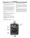
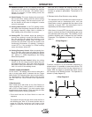
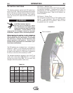
A remote control receptacle is provided on the lower
center case front of the welder for connecting a
remote control to the machine. Refer to the Optional
Accessories section of this manual for available
remote controls.
The following items can be connected to the 6 pin
socket on the front panel:
• Remote control potentiometer (K857) for Stick
welding.
•
Remote Foot Amptrol (K870), Hand Amptrol (K963-3).
• Arc Start Switch (K814).
- "&2>D;34G?;>34
8530<0643
M44? 2H;8=34A D?A867C 0=3
2708=43C>0BD??>AC
M44?2H;8=34A0F0H5A>< 0A40BF74A48C
2>D;31430<0643
M"4E4A0;;>FC74C>A27C>C>D27C742H;8=34A
M44?2H;8=34A0F0H5A><;8E44;42CA820;28A
2D8CB
///////////////////////////////////////////
+&""
%) '#""($ ) #&'(
(&#
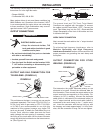
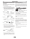
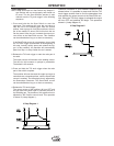
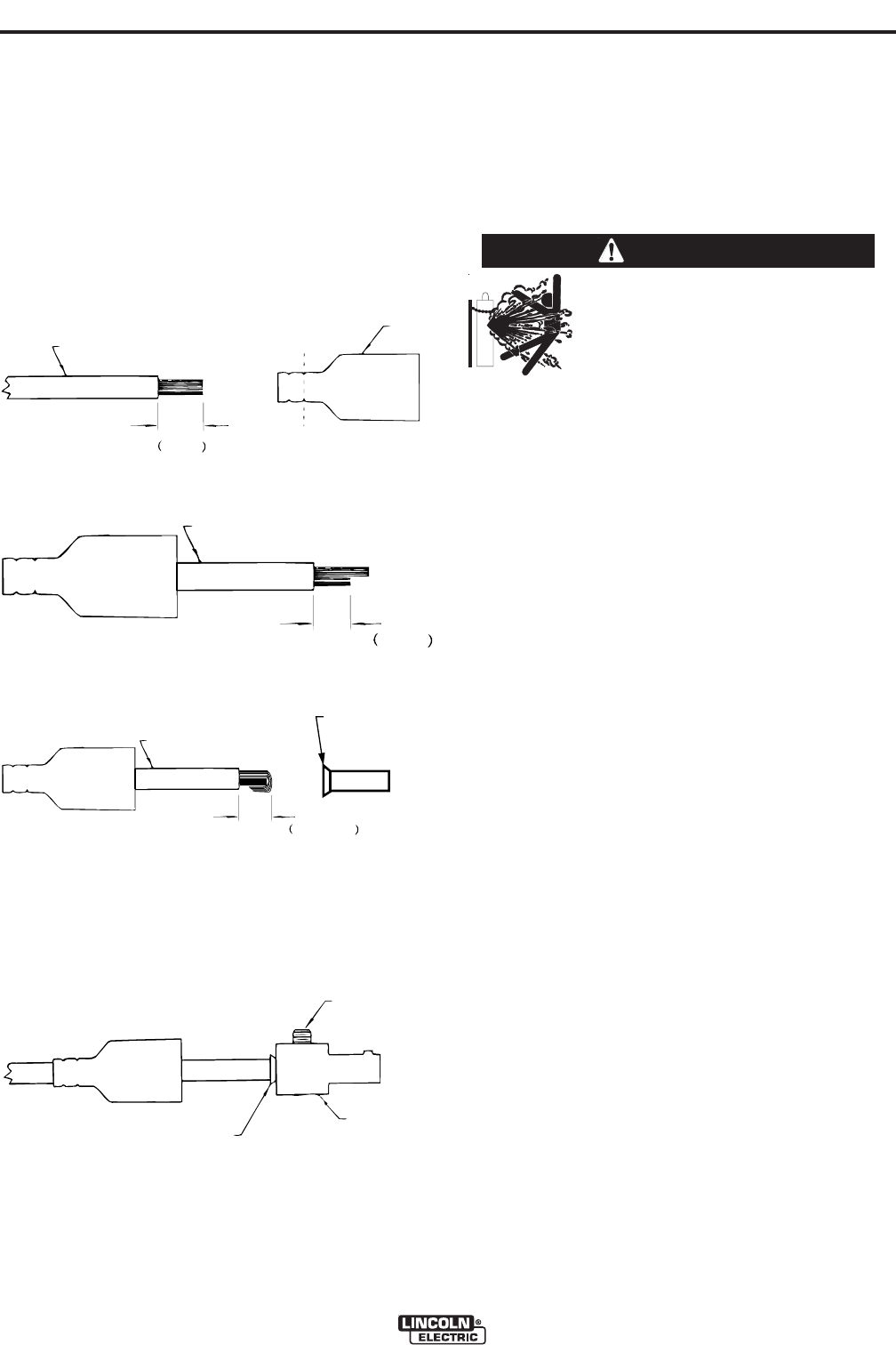
A quick disconnect system is used for the welding
cable connections. The stick electrode cable will need
to have a plug attached.
1. Cut off welding cable lug, if present.
2. Remove .75 in. (19mm) of welding cable insulation.
3. Slide rubber boot onto cable end. The boot end
may be trimmed to match the cable diameter. Use
soap or other nonpetroleum-based lubricant to
help slide the boot over the cable, if needed.
4. Cut 45-50% of the copper strands back 1/4” (6
mm).
5. Fold copper strands over cut strands and insert
into ferrule.
6. Slide the copper ferrule into the brass plug.
7. Tighten set screw to collapse copper tube. Screw
must apply pressure against welding cable. The
top of the set screw will be well below the surface
of the brass plug after tightening.
8. Slide rubber boot over brass plug. The rubber boot
must be positioned to completely cover all electri-
cal surfaces after the plug is locked into the recep-
tacle.
19 mm
.
75 in.
W
ELDING CABLE
BOOT
TRIM, IF REQ'D
TO FIT OVER CABLE
19 mm
.
75 in.
W
ELDING CABLE
BOOT
TRIM, IF REQ'D
TO FIT OVER CABLE
6 mm
.25 in.
WELDING CABLE
6 mm
.25 in.
WELDING CABLE
12 mm max.
.50 in. max
WELDING CABLE
COPPER FERRULE
12 mm max.
.50 in. max
WELDING CABLE
COPPER FERRULE
SET SCREW
BRASS PLUG
COPPER TUBE
SET SCREW
BRASS PLUG
COPPER TUBE
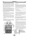
' "'#""(#"
Obtain the necessary inert shielding gas. Connect the
cylinder of gas with a pressure regulator and flow
gage. Install a gas hose between the regulator and
gas inlet (located on the rear of the welder). The gas
inlet has a 5/16-18 right hand female thread; CGA
#032.