


F-2
DIAGRAMS
F-2
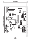
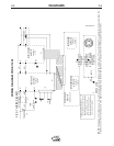
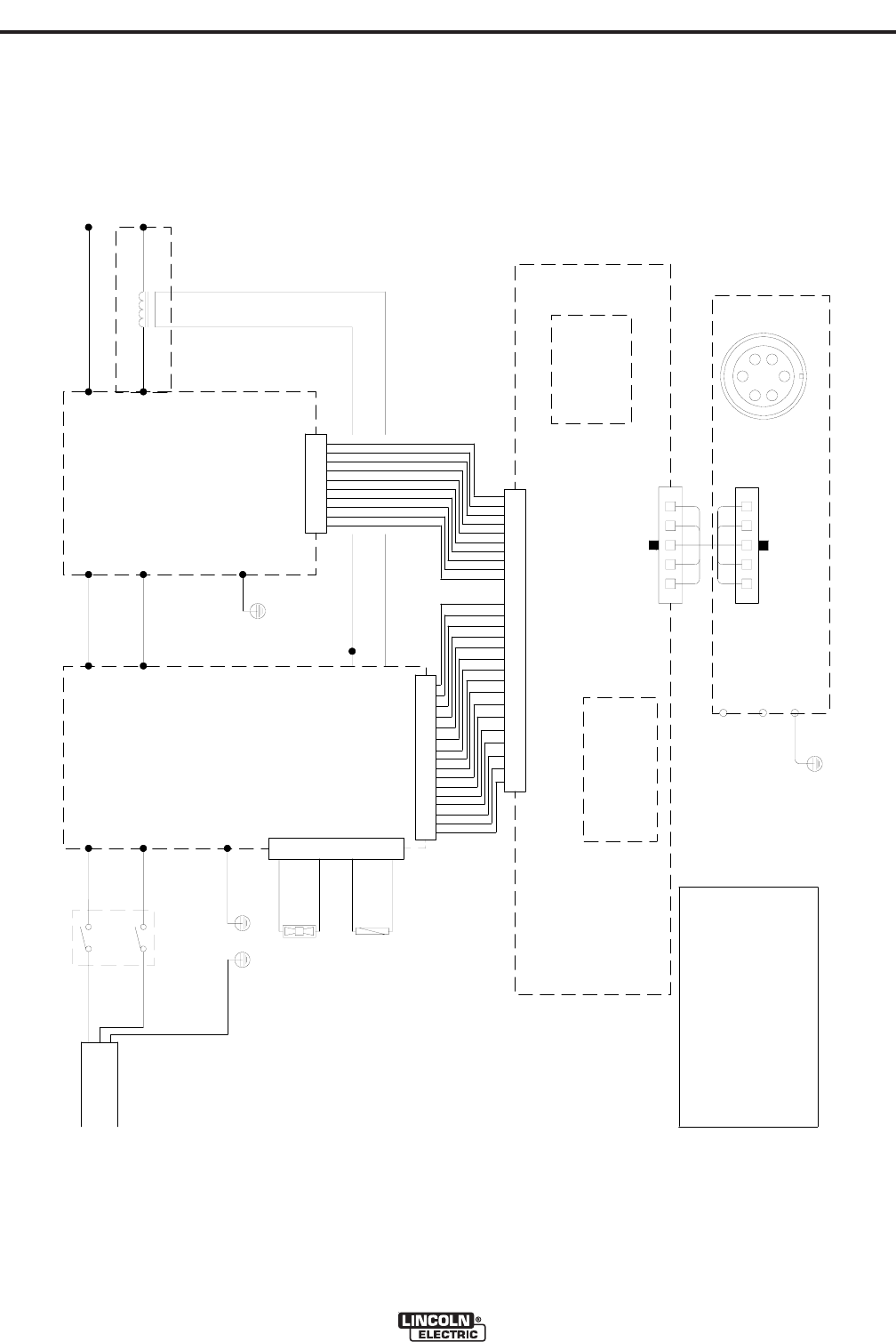
V160-T
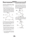
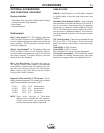
V160-T WIRING DIAGRAM
1
2
4
3
AC1
AC2
GND
S1
BLUE
BROWN
WHITE
BLACK
YELLOW / GREEN
115/230/1/50/60
Vac
FAN
JP2
DC-A
DC+
Y/G
BLACK
RED
DC+
DC-
GND
123 6541011987121513 14 16
135421067 98
JP1
JP1
1354 210 67981113 12
J1
1415161724 23 22 21 20 19 1826 25
WELD CONTROLLER
W05X0233
(SCHEMATIC:
X0233)
METER BOARD
W05X0207
(SCHEMATIC:
X0207)
W1
W2
HF1
HF2
HF TRANSFORMER
-
+
INPUT BOARD
W05X0203
(SCHEMATIC:
X0203)
INVERTER BOARD
W05X0190
(SCHEMATIC:
X0190)
1
34
2
T1
GAS
SOLENOID
W07X0262rev03
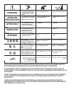
WARNING: HIGH VOLTAGE CAN KILL
* Do not operate with covers removed.
* Disconnect input power by unplugging
power cord before servicing.
* Do not touch electrically live parts.
* Only qualified persons should install,
use or service this machine.
*
(SCHEMATIC: X0322)
W05X0322
REMOTE BOARD
J1
JP1
EARTH
*
RIBBON CABLE
Y/G
DISPLAY BOARD
W05X0370
(SCHEMATIC: X0370)
OR
GREEN
WIRING DIAGRAM CODE 11032
NOTE: This diagram is for reference only. It may not be accurate for all machines covered by this manual. The specific diagram for a particular code is pasted inside the
machine on one of the enclosure panels. If the diagram is illegible, write to the Service Department for a replacement. Give the equipment code number.