


"'( (#"
*(
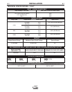
Fuse the input circuit with time delay fuses marked “D”
or delay type
1
circuit breakers. Using fuses or circuit
breakers smaller than recommended may result in
“nuisance” shut-offs from welder inrush currents even
if not welding at high currents.
1
Also called inverse time or thermal/magnetic circuit
breakers. These circuit breakers have a delay in tripping
action that decreases as the magnitude of the current
increases.
The Invertec V160-T is recommended for use on an
individual branch circuit.
*"$)(
The rated output of the V160-T is available when con-
nected to a 30A branch circuit. When connected to a
branch circuit with lower ampacity, lower welding cur-
rent and duty cycle must be used. An output guide is
provided below. The values are approximate and must
be adjusted downward if the fuse or circuit breaker
trips off. Other loads on the circuit and fuse/circuit
breaker characteristics will affect the available output.
Do not exceed these welding conditions:
?;D6>=01A0=27
10% duty cycle
Stick: 65A
TIG: 95A
?;D6>=01A0=27
10% duty cycle
Stick: 75A
TIG: 105A
?;D6>=01A0=27
10% duty cycle
Stick: 85A
TIG: 120A
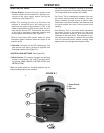
The Invertec V160-T is provided with a 115/230V
cable, 6.6ft.(2m) in length, with a 15Amp 5-15P plug
molded onto the cord.
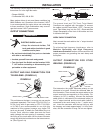
The V160-T is supplied with an additional 20A plug
that can replace the 15A plug to achieve higher out-
put. To install the supplied 20A plug:
Connect the white (neutral) wire under terminal clamp
with silver screw, and black (hot) wire under terminal
clamp with brass screw. Connect green wire under
terminal clamp with green screw.
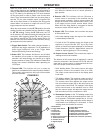
&))(#&'(#&)'
The dual input voltage machine is provided with an
ARFU device. It only operates when the input is con-
nected to an 115V supply and protects from input over
current conditions.
When the ARFU has been activated due to an input
over current condition, the output will be turned off and
the green Power LED will blink indicating an over-cur-
rent condition. This condition usually occurs when the
unit is operated beyond its rated duty cycle. The unit
will self-restore after a short time and will be ready for
normal operation once the green Power LED stops
blinking and remains on.
NOTE: The ARFU replaces a fuse (F2) that was used
in older V160’s.
•
08;DA4C>F8A40B8=BCAD2C43<0H20DB4?4AB>=0;
8=9DAH>A30<064C>4@D8?<4=C(>148=BC0;;43>A
2742:431H0=4;42CA8280=>A@D0;85843?4AB>=
>=;H
---------------------------------------------------------------------------
*"$)(
To achieve the full output capacity of the V160-T,
230VAC inputs should be used. The change over is
accomplished by replacing the 115VAC plug with a 30
Amp 230VAC plug (NEMA 6-30P).
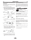
((!"($ )
In all cases, the green or green/yellow grounding wire
must be connected to the grounding pin of the plug, usu-
ally identified by a green screw.
All attachment plugs must comply with the Standard for
Attachment Plugs and Receptacles, UL498.
The product is considered acceptable for use only when
an attachment plug as specified is properly attached to
the supply cord.
The Invertec V160-T will auto reconnect to either 115V
or 230V supplies.
""&*""&(#&
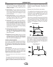
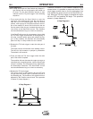
For use on engine drives, keep in mind the above
input draw restrictions and the following precaution.
The Invertec V160-T can be operated on engine driv-
en generators as long as the 230 volt auxiliary meets
the following conditions:
• The AC waveform peak voltage is below 400 volts*.
• The AC waveform frequency is between 45 and
65Hz.
• The RMS voltage of the AC waveform is always
greater than 208VAC *.
* for 115 VAC input divide these values in half.
+&""