


#$&(#"
$'F8C27)?B;>?4(8<4A
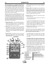
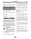
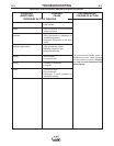
These control the upslope timer for TIG welding
(used only on "T" type machines). The following
table shows the DIP Switch settings and selected
upslope time.
$'F8C27 $'F8C27 )?B;>?4(8<4
ON ON 0.1 seconds
OFF OFF 0.5 seconds
ON OFF 1 second
OFF ON 4 seconds
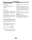
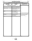
'C0ACA0C4ADAA4=C39DBC<4=C
The start/crater current of a "T" type machine can be
changed if necessary. The values are set from the fac-
tory.
European Machines:
20% (160A welding current = 32A start/crater current)
USA Machines:
10% (160A welding current = 16A start/crater current)
4BDA4C70C0;;8=BC0;;0C8>=>?4A0C8>=<08=C4
=0=240=3A4?08A?A>243DA4B0A4?4A5>A<43>=;H
1H@D0;858438=38E83D0;B 8=2>;=;42CA828B=>C
A4B?>=B81;45>A30<064B20DB431H8<?A>?4A
8=BC0;;0C8>=8<?A>?4A20A4>A01=>A<0;>?4A0C8>=
(78B039DBC<4=C?A>243DA4<DBC14?4A5>A<43
>=;H1H 8=2>;=CA08=43B4AE824C427=8280=B(74
<0278=4F8;;14>?4A0C8=6F8C7C742>E4AA4<>E43
F74A48C8B?>BB81;4C>2><48=2>=C02CF8C77867
E>;C064B&4030;;C745>;;>F8=68=BCAD2C8>=B
145>A4BC0AC8=6C74?A>243DA4
(&'#"
M+4;38=64@D8?<4=C64=4A0C4B7867
E>;C064B
M>=>CC>D27C74;8E4?0ACB>5C74
<0278=4C744;42CA>34C74F>A:
2;0<?>A2>==42C43F>A:?8424B
F74=C78B4@D8?<4=C8B>=
M=BD;0C4H>DAB4;55A><;8E44;42CA820;2>==42
C8>=BC744;42CA>34C74F>A:2;0<?0=3C74
2>==42C43F>A:?8424B
-----------------------------------------------------------------------
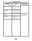
1. Remove the cover of the machine to access the
control Printed Circuit Boards on the case front.
2. To adjust the start/crater current, output current
from the machine must flow through a load bank or
a TIG arc. Connect the necessary equipment. In
both cases, load bank or TIG arc, a trigger must be
connected to the machine. If a load bank is used, it
must be setup for 160A and approximately 25V.
3. Make sure all electrical connections are free from
contact with other parts of the machine. Reconnect
the case back if necessary. Turn ON the machine.
4. On the control panel of the machine, select the fol-
lowing:
• Mode Switch: LIFT TIG (Do not use HF TIG or
damage to measuring equipment will occur.)
• Trigger Mode: 4 Step
• Pulsing: OFF
• Output Current: Maximum (160A)
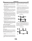
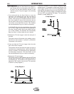
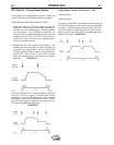
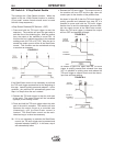
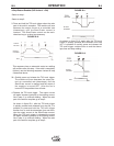
5. Activate the trigger of the machine to achieve the
start or crater current portion of the welding
sequence. Refer to the trigger sequences explained
above if more information is needed.
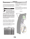
6. In this condition, measure the output current of the
machine and adjust the start/crater current as nec-
essary. The calibration trimmer for the start/crater
current is located on the left side of the machine (as
viewed from the front) on the display board. The
access hole for this trimmer is the higher one on the
display board. (Do not adjust the lower trimmer on
the display board; this is the output current calibra-
tion.)
The output current is set to 160A, therefore the
start/crater current calibration will be a percentage
of this 160A setting. Use the following equation for
determining the desired start/crater current calibra-
tion:
Desired start/crater current percentage multiplied
by 160 = calibration current.
For example, to calibrate the machine for 15%
start/crater current, multiply this by 160 to get the
calibration current ( 0.15 x 160 = 24).
7. Release the trigger to turn off the output of the
machine. Turn OFF the machine and disconnect it
from the input source. Reassemble the machine
making sure the ground wire to the cover is con-
nected.
*(
+&""