


P 17/ 25
Repair
DISASSEMBLING
ASSEMBLING
Fig. 52
Fig. 53
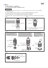
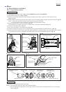
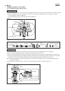
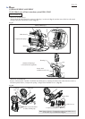
(6) Remove Stop ring EXT U-6 from Can shaft, then separate Flat washer 7, Spur gear 10 and Clutch cam A from Can shaft.
(7) Receive Spiral bevel gear 32 on 1R139 put on U-groove of Arbor press table and press out Cam shaft with 1R281
(ø7mm round bar) as drawn in Fig. 52.
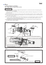
The swash bearing section can be removed as drawn in Fig. 53.
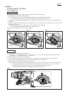
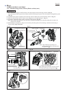
Assemble the Swash bearing section carefully to the directions of each part and the order shown in Fig. 53.
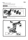
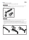
(1) Pass Cam shaft through Clutch cam A, and then receive Clutch cam A on 1R035.
(2) Pass Cam shaft through Swash bearing 10 and press-fit Spiral bevel gear 32 to Cam shaft until Spiral bevel gear stops.
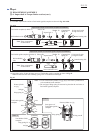
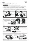
(3) Pass Cam shaft through Ring 8 and Bearing retainer B, and then press-fit Ball bearing 608ZZ and Ring 8 to Cam shaft
with 1R033 carefully. Do not pinch Bearing retainer B by Ball bearing 608ZZ and Spiral bevel gear 32.
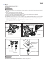
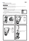
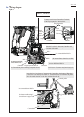
Note: When 1mm height of Cam shaft is projected out over Ring 8, the assembling work is successful. (Fig. 54) Check
the height at this time.
(4) Set Spur gear 10 and Flat washer 7 in place on Cam shaft, and secure them with Stop ring EXT U-6.
[3] DISASSEMBLY/ASSEMBLY
[3]-7. Swash bearing section (cont.)
Stop ring
EXT U-6
Flat washer 7 Bearing retainer BSpur gear 10
Arbor press
1R139
Clutch cam A Swash bearing 10 Spiral bevel gear 32
Cam shaft Ring 8
(Flat shape)
Ring 8
(stepped)
Ball bearing 608ZZ
Spiral bevel gear 32
Arbor press table
1R281
1mm height
Cam shaft
Arbor press
Top of Ring 8
Fig. 54
Bearing retainer B Spiral bevel gear 32
1R033
1R035
Clutch cam A