


P 24/ 25
BHR242, BHR243
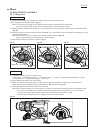
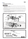
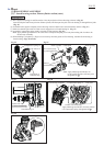
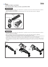
Lead wires to Connector have to be routed
between Rib B and Rib D.
Lead wires to Connector and Stator lead wires
have to be routed between Rib A and Rib B.
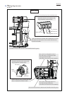
Route the lead wires between Connector and Controller to the bottom of Housing L
so as not to rise on the top line of Rib C. Turn them back to set Connector in place.
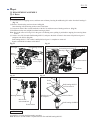
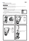
Place the turned portion over the line extended from Rib D.
Do not put Stator lead wires on Rib C.
Rib D
Rib C
Rib B
Line extended from Rib D
Line extended from Rib D
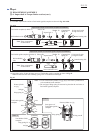
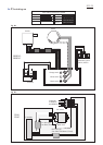
Wiring diagram
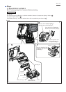
Fig. D-3
Rib C
Rib D
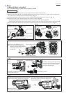
Turned portion
Connector
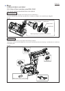
Flag receptaclesController
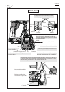
Set Controller in place with Flag receptacles faced
as drawn above.
Rib A
Connector
Controller
The bottom of Housing L
viewed from the upper side
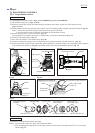
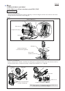
Terminal
Connect Lead wires to Controller/ Terminal
with Flag receptacles as drawn below.
Controller
Black
lead wire
Red
lead wire
Orange
lead wire
Black
lead wire
White
lead wire
Flag receptacles
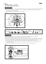
Slacks of Lead wires between Controller and
Connector/ Stator have to be placed over the line
extended from Rib D.
Stator
Terminal
Do not put any lead
wires on this boss.