


P 25/ 25
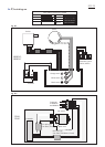
Wiring diagram (cont.)
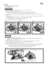
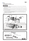
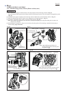
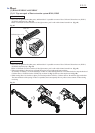
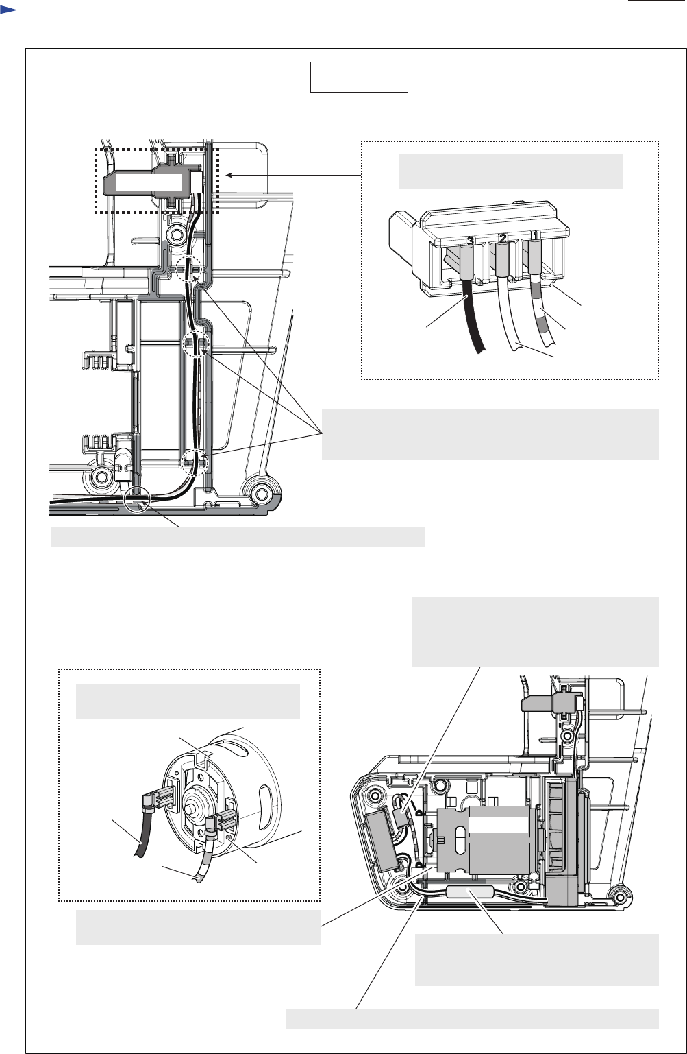
Fig. D-4
DX01, DX02
Red mark
Black lead wire
Connector viewed from lead wire installation side
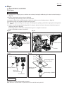
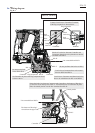
Lead wires between Connector and Controller have to fixed
with these lead wire holders. Do not slack them between
the lead wire holders.
Connector
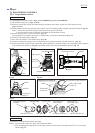
Red lead wire
White lead wire
DC motor
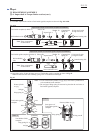
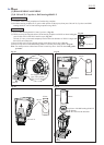
Connect Lead wires to DC motor with
Flag receptacles as drawn below.
Connect Lead wires to Connector with
Flag receptacles as drawn below.
Black
Lead wire
Red
Lead wire
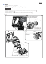
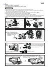
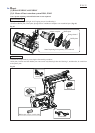
Pass Lead wires through the holes of
Line filter one by one and place them
in the space between Ribs.
(Line filter is not used for some countries.)
Pass Lead wires through the hole of
Line filter and place them here.
(Line filter is not used for some countries.)
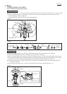
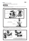
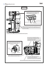
DC motor
Put Lead wires between Connector and Controller into this groove.Put Lead wires between Connector and Controller into this groove.
Put Lead wires between Connector and Controller into this groove.
Connector
Set DC motor in place so that the red mark
faces to the bottom of DX01/ DX02.