


OM-2221 Page 16
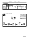
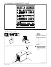
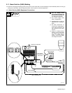
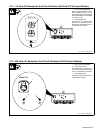
3-9. Selecting AC or DC Output
! Turn Off welding power
source and disconnect input
power before relinking unit.
Remove top of unit.
1 AC/DC Output Selection
Label (Located Inside Unit)
2 Jumper Links
Locate terminal board inside unit.
Install jumper links for desired out-
put as shown on label.
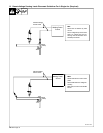
. Securing nuts must be re-
moved to change the position
of the three jumper links at the
right of the terminal board. To
change the position of the re-
maining six jumper links, loos-
en the securing nuts only to al-
low the slotted jumper links to
be moved. Always securely re-
tighten nuts after links are
moved.
Reinstall top of unit.
! See Safety Rules at begin-
ning of manual for special
AC concerns.
801 881-A / Ref. S-185 482
AC
DC
1
2
Tools Needed:
3/8, 11/16, 7/8 in
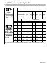
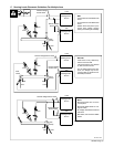
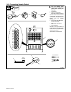
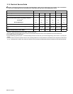
3-10. Terminal Strip TE3 and Remote 14 Receptacle RC7 Information
Socket
on RC7
Terminal
on TE3
Information
24 VOLTS AC
A A 24 volts, 12 amperes, AC. Protected by circuit breaker CB2.
24 VOLTS AC
B B Contact closure to A completes 24 volts AC contactor control circuit.
C C Command reference; +10 volts DC.
REMOTE OUTPUT CONTROL
D D Remote control circuit common.
E E 0 to +10 volts DC input command signal from remote control.
115 VOLTS AC
I I 115 volts, 12 amperes AC. Protected by circuit breaker CB1.
115 VOLTS AC
J J Contact closure to I completes 115 volts AC contactor control circuit.
GND
K
G
K
G
Chassis common.
Circuit common for 24, 42 and 115 volts AC circuits.
42 VOLTS AC
* L
42 volts, 12 amperes AC. Protected by circuit breaker CB3.
A/V AMPERAGE
F * Current feedback; +1 volt DC per 100 amperes.
A/V AMPERAGE
VOLTAGE H * Voltage feedback; +1 volt DC per 10 output terminal volts.
REMOTE VOLTAGE SENSING
* N Voltage sensing signal from Work weld output terminal.
REMOTE VOLTAGE SENSING
* P Voltage sensing signal from Electrode weld output terminal.
* Not Used