


OM-2221 Page 28
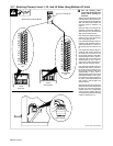
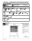
4-4. Using AC Arcs Terminal Strip TE4 Connections
! Turn Off welding power
source and disconnect input
power before opening ac-
cess door.
! DC output units do not re-
quire synchronization with
AC output units.
! If there are any questions re-
garding this procedure, con-
tact the factory before con-
necting units.
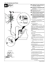
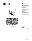
1 Terminal Strip TE4
This procedure allows the AC out-
put waveforms of two or more units
to have a phase shift. Make con-
nections between terminal strip
TE4 on applicable AC output units
as shown in illustration.
. Do not disturb factory connec-
tions to terminal strip TE4.
! Ensure that primary input
power conductors are con-
nected to each unit in the
same sequence (L1 to L1, L2
to L2, and L3 to L3). See Sec-
tion 3-16 for information on
connecting input power. See
Section 3-17 for information
on testing for proper primary
phase sequence.
2 Lead Being Connected To
TE4
3 Securing Screw
Strip 3/8 in (10 mm) insulation off
end of lead, insert end into proper
location on TE4, and tighten appli-
cable securing screw.
Close and secure access door.
. Connect plug as shown in Sec-
tion 4-5.
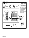
Tools Needed:
A
B
C
1
D
E
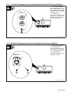
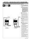
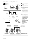
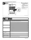
Terminal Strip TE4 Connections For Running Multiple AC Arcs
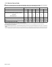
AC Waveforms
Waveform 1
Waveform 2
Phase Shift
Connections from first to second
welding power source:
terminal A to terminal E,
terminal C to terminal C
A
B
C
D
E
A
B
C
D
E
A
B
C
D
E
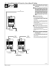
TE4 on first welding
power source
TE4 on second welding
power source
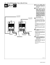
TE4 on third welding
power source
Repeat same connection sequence
on following welding power sources
Connections from second to third
welding power source:
terminal A to terminal E,
terminal C to terminal C
Connections from third to fourth
welding power source:
terminal A to terminal E,
terminal C to terminal C
Ref. 801 882-A
2
3
1
3/8 in
(10 mm)
. Use two-conductor (12 to 20 gauge) with uninsulated ground,
shielded cable to make TE4 connections. Connect uninsulated
ground wire to terminal C on TE4.