


OM-2221 Page 33
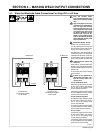
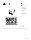
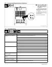
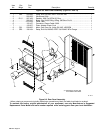
6-3. Access Area Supplementary Protectors
! Turn Off welding power
source and disconnect input
power before checking cir-
cuit breakers.
1 Supplementary Protector CB2
CB2 protects the 24 VAC portion of
terminal strip TE3 and the Remote
14 receptacle.
2 Supplementary Protector CB3
CB3 protects the 42 VAC portion of
terminal strip TE3.
Press button to reset breaker.
Ref. 175 086 / 801 882-A
1
2
CB2
CB3
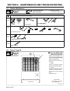
6-4. Troubleshooting
Trouble Remedy
No weld output; unit completely in-
operative.
Place line disconnect switch in On position (see Section 3-16).
Check fuses F1 and F2 and replace if necessary (see Section 6-2).
Check and replace line fuse(s), if necessary, or reset circuit breaker (see Section 3-16).
Check for proper input power connections (see Section 3-16).
No weld output; pilot light On. Check, repair, or replace remote control.
Unit overheated. Allow unit to cool with fan On (see Section 3-2).
Have Factory Authorized Service Agent check control board PC1.
Erratic or improper weld output. Use proper size and type of weld cable (see Section 3-8).
Clean and tighten all weld connections.
When using multiple units, make sure all units connected with terminal strip TE4 are turned on.
Have Factory Authorized Service Agent check control board PC1.
No 115 volts AC output at duplex
receptacle, terminal strip TE3, and Re-
mote 14 receptacle.
Reset supplementary protector CB1 (see Section 3-13).
No 230 volts AC output at duplex re-
ceptacle.
Reset supplementary protector CB4 (see Section 3-14).
No 24 volts AC output at terminal strip
TE3 and Remote 14 receptacle.
Reset supplementary protector CB2 (see Section 6-3).
No 42 volts AC output at terminal strip
TE3.
Reset supplementary protector CB3 (see Section 6-3).