


OM-2221 Page 29
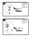
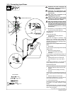
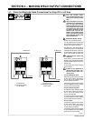
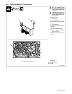
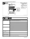
4-5. Control Board PC1 Connections
! Turn Off welding power
source and disconnect input
power before following this
procedure.
! If there are any questions re-
garding this procedure, con-
tact the factory before con-
necting units.
Remove top cover.
1 Front Panel
2 Control Board PC1
PC1 is mounted on inside of control
panel.
3 Receptacle RC4
PC1 arrives from the factory with a
66/34 plug.
Plugs are labeled accordingly.
. Always keep disconnected
plug for future use.
Reinstall circuit card cover and top
cover.
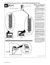
Tools Needed:
1
3/8 in
2
PC1 Viewed From Rear Of Unit
Ref. 801 982-A
2
3