


OM-2221 Page 23
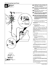
3-16. Connecting Input Power
input_2 3/96 - Ref. 144 221 / Ref. 801 883-B
3/8 in
Tools Needed:
7/16 in
3/16 in
1
2
3
5
L3 (W)
L1 (U)
L2 (V)
7
10
8
4
9
6
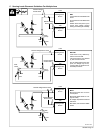
! Installation must meet all National and
Local Codes − have only qualified per-
sons make this installation.
! Disconnect and lockout/tagout input
power before connecting input conduc-
tors from unit.
! Make input power connections to the
welding power source first.
! Always connect green or green/yellow
conductor to supply grounding terminal
first, and never to a line terminal.
! When using multiple units which will be
linked with the synchronizing terminal
strip TE4, ensure that primary input pow-
er conductors are connected to each unit
in the same sequence (L1 to L1, L2 to L2,
and L3 to L3.)
. See Section 3-17 for information on testing
for proper primary phase sequence.
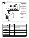
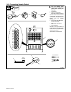
See rating label on unit and check input voltage
available at site.
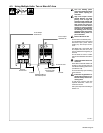
Remove left side panel.
1 Input Power Conductors (Customer
Supplied Cord)
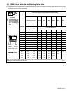
Select size and length of conductors using
Section 3-15. Conductors must comply with
national, state, and local electrical codes. If
applicable, use lugs of proper amperage capac-
ity and correct hole size.
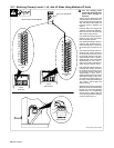
Welding Power Source Input Power Connec-
tions
2 Strain Relief
Route conductors (cord) through strain relief and
tighten screws.
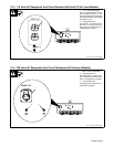
3 Machine Grounding Terminal
4 Green Or Green/Yellow Grounding
Conductor
Connect green or green/yellow grounding con-
ductor to welding power source grounding termi-
nal first.
5 Welding Power Source Line Terminals
6 Input Conductors L1 (U), L2 (V) And L3
(W)
Connect input conductors L1 (U), L2 (V) and L3
(W) to welding power source line terminals.
Reinstall left side panel.
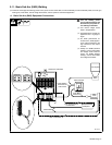
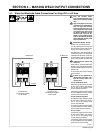
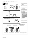
Disconnect Device Input Power Connections
7 Disconnect Device (switch shown in OFF
position)
8 Disconnect Device (Supply) Grounding
Terminal
Connect green or green/yellow grounding con-
ductor to disconnect device grounding terminal
first.
9 Disconnect Device Line Terminals
Connect input conductors L1 (U), L2 (V) And L3
(W) to disconnect device line terminals.
10 Overcurrent Protection
Select type and size of overcurrent protection us-
ing Section 3-15 (fused disconnect switch
shown).
Close and secure door on line disconnect de-
vice. Remove lockout/tagout device, and place
switch in the On position.
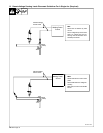
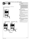
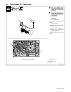
= GND/PE Earth Ground
4
6
Input Contactor
3
GND/
PE Earth Ground
=