


OM-2221 Page 24
Unit B
(Second Unit)
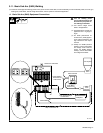
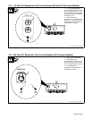
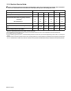
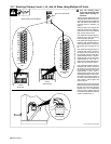
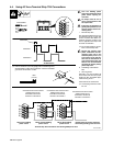
3-17. Matching Primary Lines L1, L2, And L3 When Using Multiple AC Units
Set on AC Volts Scale
Meter Polarity Does Not Matter
Ref. 801 882-A / Ref. 801 883-B
Unit A
(First Unit)
L1
L2
L3
A
B
C
D
E
G
I
J
K
L
N
P
Terminal Strip
TE3
A
B
C
D
E
G
I
J
K
L
N
P
Terminal Strip
TE3
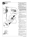
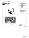
Input Contactor
! Turn Off welding power
source and disconnect input
power before opening ac-
cess door.
This test must be performed on the
units that will be interconnected us-
ing the synchronizing terminal strip
TE4. This refers to the multiple unit
hook-ups shown in Sections 4-2
and 4-3.
Power On both units. Using an AC
voltmeter, measure the voltage be-
tween terminal A of terminal strip
TE3 on both units as shown.
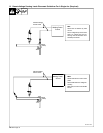
If the measured voltage is approxi-
mately 0 (zero) volts, the primary
lines are properly phased.
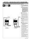
If the measured voltage is approxi-
mately 53 volts, swap the input con-
ductor connections to L1 and L3 on
the primary input contactor of unit
B.
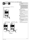
If the measured voltage is approxi-
mately 46 volts, swap L1 and L2 on
the primary input contactor of unit
B. The meter will then read either
approximately 53 volts or approxi-
mately 26 volts. If the meter reads
approximately 53 volts, swap L1
and L3. If the meter reads approxi-
mately 26 volts, swap L2 and L3.
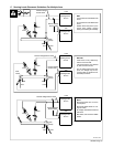
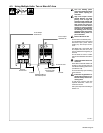
If the measured voltage is approxi-
mately 26 volts, swap L1 and L2 on
the primary input contactor of unit
B. The meter will then read either
approximately 0 (zero) volts or
approximately 46 volts. If the meter
reads approximately 0 volts, the pri-
mary lines are properly phased. If
the meter reads approximately 46
volts, swap L1 and L2 again, and
swap L2 and L3.
When the second unit’s primary line
phase sequences are matched with
the first unit, test primary phasing
between third unit (if applicable)
and second unit. Always test and
correct phasing between following
unit and unit previous to it.