


OM-2221 Page 31
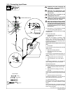
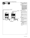
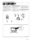
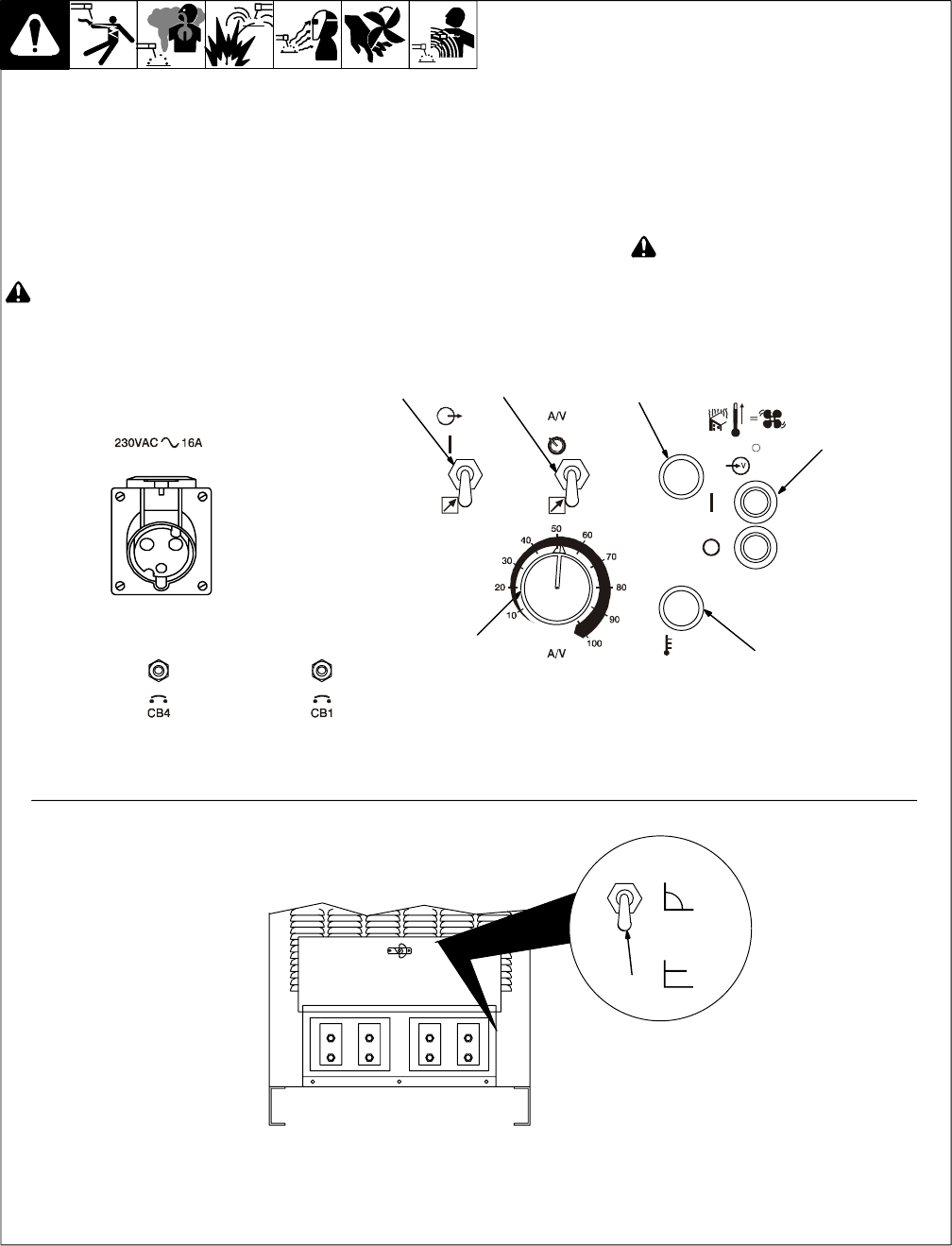
5-2. Front Panel Controls (CE Models)
1 Output Control Switch
For weld output, place switch in On position.
For remote control of output, make connec-
tions to terminal strip TE3 or Remote 14 re-
ceptacle (see Section 3-10) and place switch
in Remote position.
2 A/V (Amperage/Voltage) Control Switch
For front panel control, place switch in Panel
position and use the A/V Adjust control.
! Turn Off power before connecting re-
mote device.
For remote control, connect remote device to
terminal strip TE3 or Remote 14 receptacle,
and place switch in Remote position. Remote
control provides full range of unit output re-
gardless of A/V Adjust control setting
3 Pilot Light
4 Power Push Button Switch
. The fan motor is thermostatically
controlled and only runs when cooling is
needed.
5 High Temperature Shutdown Light
Lights if welding power source overheats.
6 A/V (Amperage/Voltage) Adjustment
Control
Use control to select weld voltage or amper-
age. Control may be adjusted while welding.
Numbers on scale are for reference only.
7 CC/CV Switch (Mounted Inside Access
Area)
! Turn Off welding power source before
opening access door to change switch
position.
Place switch in desired position.
Ref. 175 086 / Ref. 801 882-A
1
2
4
6
3
5
CC
CV
7