


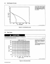


2-1.
Volt-Ampere
Curves
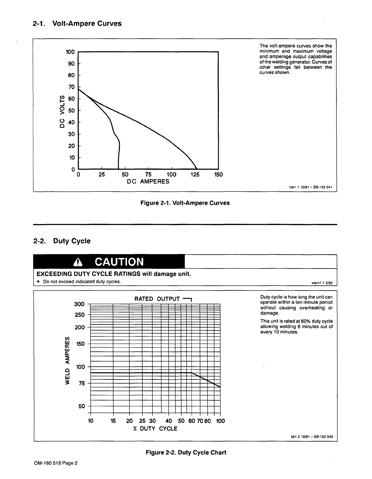
Figure
2-1.
Volt-Ampere
Curves
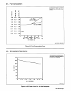
2-2.
Duty
Cycle
a
CAUTION
300
-
250
-
200
U)
150
w
a
<
100
.
75
.
Figure
2-2.
Duty
Cycle
Chart
Cl)
0
>
0
100
90
80
70
60
50
40
30
20
10
0
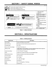
The
volt-ampere
curves
show
the
minimum
and
maximum
voltage
and
amperage
output
capabilities
of
the
welding
generator.
Curves
of
other
settings
fall
between
the
curves
shown.
rsDl.1
10/91
SB-152
541
0
25
50
75
100
125
150
DC
AMPERES
EXCEEDING
DUTY
CYCLE
RATINGS
will
damage
unit.
Do
not
exceed
indicated
duty
cycles.
warn7.1
2/92
This
unit
is
rated
at
60%
duty
cycle
allowing
welding
6
minutes
out
of
every
10
minutes.
RATED
OUTPUT
~......,
50-
---
--
10
15
20
25
30
40
50
60
7080
100
Duty
cycle
is
how
long
the
unit
can
operate
within
a
ten
minute
period
without
causing
overheating
or
damage.
%
DUTY
CYCLE
sbl.2
10/91
SB-152
540
OM-160
518
Page
2