


3-3.
Grounding
The
Generator
Auxiliary
Power
System
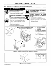
3-4.
Connecting
To
Weld
Output
Terminals
a
WARNING
~-
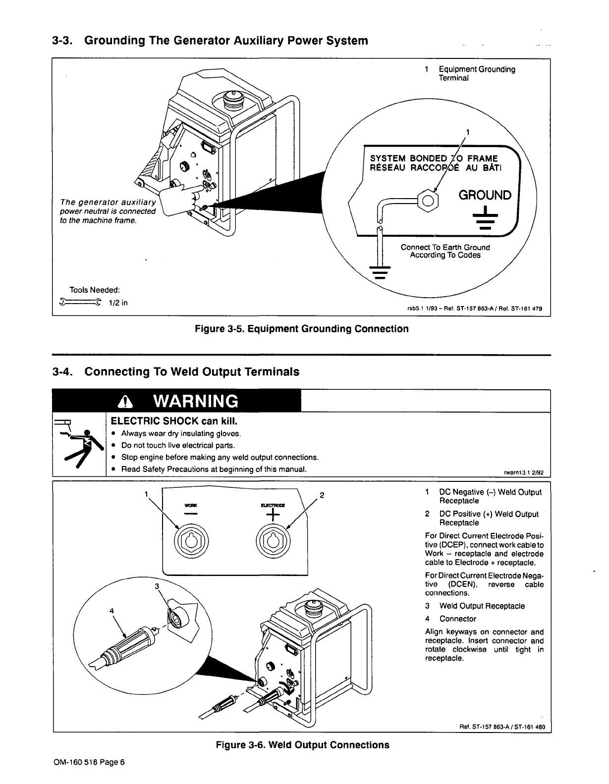
1
Equipment
Grounding
Terminal
The
generator
auxiliary
power
neutral
is
connected
to
the
machine
frame.
Tools
Needed:
-.~
rsb5.1
1/93
Ret.
ST-i
~7
863-A
/
Ret.
ST-I
81
479
Figure
3-5.
Equipment
Grounding
Connection
.
.~
ELECTRIC
SHOCK
can
kill.
Always
wear
dry
insulating
gloves.
Do
not
touch
live
electrical
parts.
Stop
engine
before
making
any
weld
output
connections.
Read
Safety
Precautions
at
beginning
of
this
manual.
rwarnl3,l
2/92
1
~
~
2
~
I
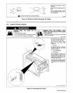
DC
Negative
()
Weld
Output
Receptacle
2
DC
Positive
(+)
Weld
Output
Receptacle
For
Direct
Current
Electrode
Posi
tive
(DCEP).
connect
work
cable
to
Work
receptacle
and
electrode
cable
to
Electrode
+
receptacle.
For
Direct
Current
Electrode
Nega
tive
(DCEN),
reverse
cable
connections.
3
Weld
Output
Receptacle
4
Connector
Align
keyways
on
connector
and
receptacle.
Insert
connector
and
rotate
clockwise
until
tight
in
receptacle.
Figure
3-6.
Weld
Output
Connections
Ret.
ST-I57863-A/ST-161
480
OM-160
518
Page
6