


. A complete Parts List is available at www.MillerWelds.com
OM-4430 Page 22
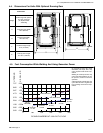
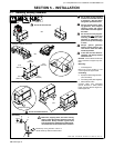
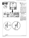
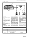
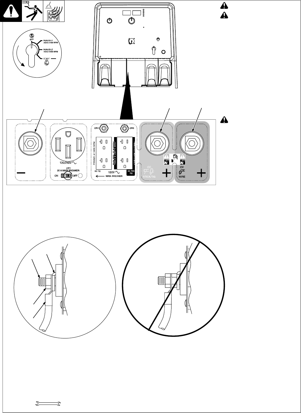
5-5. Connecting To Weld Output Terminals
! Stop engine.
! Do not connect to CC and CV
terminals at the same time.
1 Negative (−) Weld Output
Terminal
2 Stick/TIG (CC) Weld Output
Terminal
3 Wire /CV Weld Output Terminal
For MIG welding, connect work cable
to Negative (−) terminal and wire
feeder cable to Wire (CV) terminal.
For Stick welding, connect work
cable to Negative (−) terminal and
electrode holder cable to Stick/TIG
(CC) terminal.
For TIG welding, connect work cable
to Stick/TIG (CC) terminal and elec-
trode holder to Negative (−) terminal.
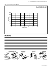
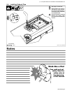
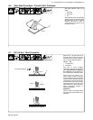
! Failure to properly connect
weld cables may cause exces-
sive heat and start a fire, or
damage your machine.
4 Weld Output Terminal
5 Supplied Weld Output Terminal
Nut
6 Weld Cable Terminal
7 Copper Bar
Remove supplied nut from weld out-
put terminal. Slide weld cable termi-
nal onto weld output terminal and se-
cure with nut so that weld cable termi-
nal is tight against copper bar. Do not
place anything between weld
cable terminal and copper bar.
Make sure that the surfaces of the
weld cable terminal and copper
bar are clean.
216 172-D / 803 984−A / 803 778-A
Tools Needed:
7
5
6
Do not place
anything between
Correct Installation Incorrect Installation
4
weld cable terminal
and copper bar.
3/4 in
32
1