


. A complete Parts List is available at www.MillerWelds.com
OM-4430 Page 23
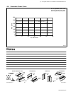
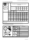
5-6. Selecting Weld Cable Sizes*
Weld Output
Terminals
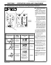
!
Weld Cable Size** and Total Cable (Copper) Length in Weld Circuit
Not Exceeding***
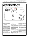
! Stop engine before
connecting to weld
output terminals.
! Do not use worn,
damaged, under-
sized, or poorly
spliced cables.
100 ft (30 m) or Less
150 ft
(45 m)
200 ft
(60 m)
250 ft
(70 m)
300 ft
(90 m)
350 ft
(105 m)
400 ft
(120 m)
Welding
Amperes
10 − 60%
Duty
Cycle
60 − 100%
Duty
Cycle
10 − 100% Duty Cycle
100 4 (20) 4 (20) 4 (20) 3 (30) 2 (35) 1 (50) 1/0 (60) 1/0 (60)
150 3 (30) 3 (30) 2 (35) 1 (50) 1/0 (60) 2/0 (70) 3/0 (95) 3/0 (95)
200 3 (30) 2 (35) 1 (50) 1/0 (60) 2/0 (70) 3/0 (95) 4/0 (120) 4/0 (120)
250 2 (35) 1 (50) 1/0 (60) 2/0 (70) 3/0 (95) 4/0 (120)
2 ea. 2/0
(2x70)
2 ea. 2/0
(2x70)
300 1 (50) 1/0 (60) 2/0 (70) 3/0 (95) 4/0 (120)
2 ea. 2/0
(2x70)
2 ea. 3/0
(2x95)
2 ea. 3/0
(2x95)
350 1/0 (60) 2/0 (70) 3/0 (95) 4/0 (120)
2 ea. 2/0
(2x70)
2 ea. 3/0
(2x95)
2 ea. 3/0
(2x95)
2 ea. 4/0
(2x120)
400 1/0 (60) 2/0 (70) 3/0 (95) 4/0 (120)
2 ea. 2/0
(2x70)
2 ea. 3/0
(2x95)
2 ea. 4/0
(2x120)
2 ea. 4/0
(2x120)
* This chart is a general guideline and may not suit all applications. If cable overheats, use next size larger cable.
**Weld cable size (AWG) is based on either a 4 volts or less drop or a current density of at least 300 circular mils per ampere.
( ) = mm
2
for metric use S-0007-F
***For distances longer than those shown in this guide, call a factory applications representative at 920-735-4505.
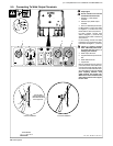
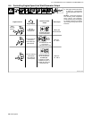
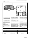
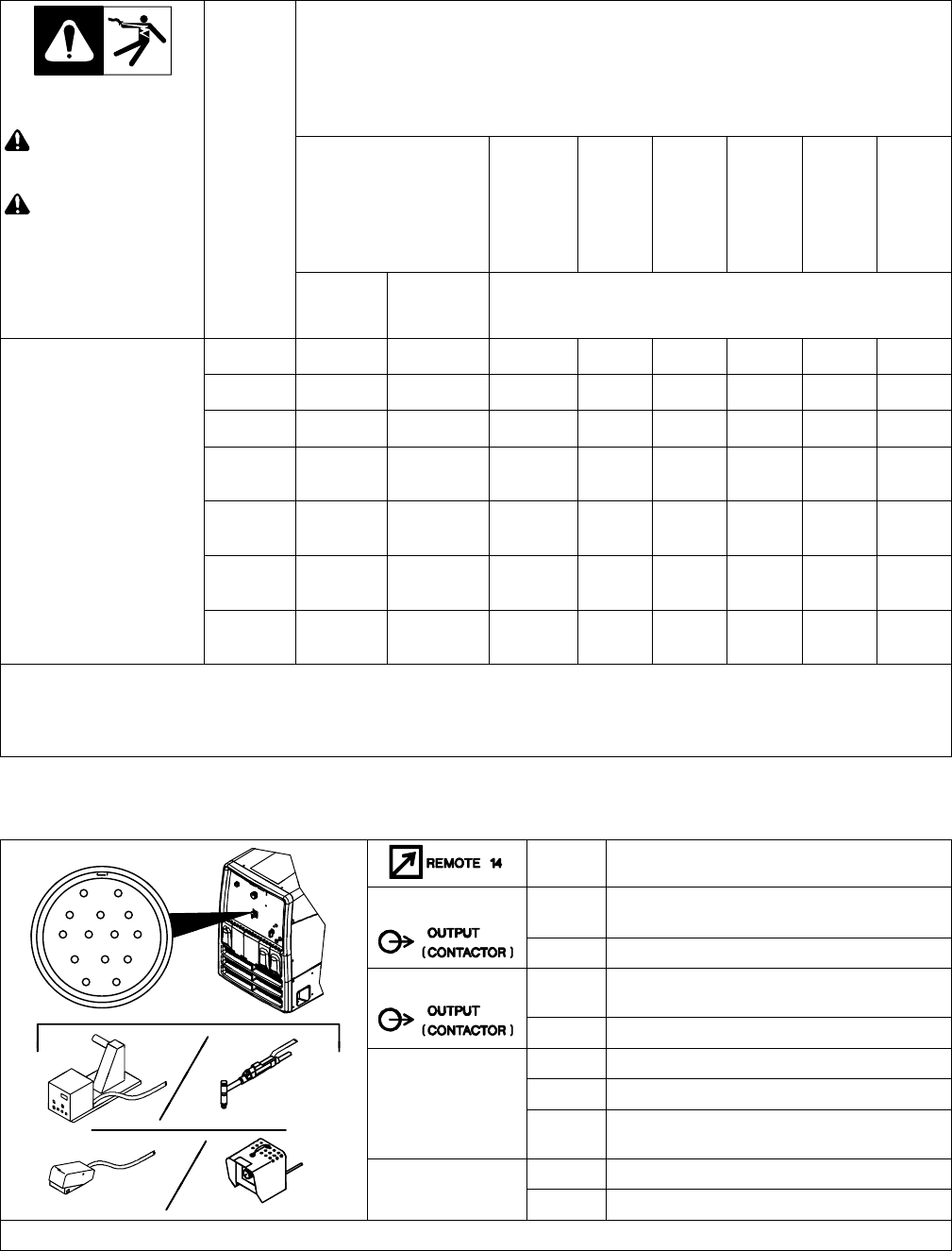
5-7. Remote Receptacle Information
. Engine runs at weld speed (3000 or 3600 rpm) whenever a device connected to the remote receptacle is running.
Socket* Socket Information
AJ
B
K
I
L
NH
24 VOLTS AC
A 24 volts ac. Protected by supplementary protector
CB4.
C
L
NH
D
M
G
B Not used.
D
M
G
E
F
115 VOLTS AC
I 115 volts ac. Protected by supplementary protec-
tor CB3.
J Not used.
A/V
C +10 volts dc output to remote control.
A/V
AMPERAGE
D Remote control circuit common.
AMPERAGE
VOLTAGE
E 0 to +10 volts dc input command signal from
remote control.
GND
G Circuit common for 24 and 115 volts ac circuits.
GND
K Chassis common.
*The remaining sockets are not used.