


. A complete Parts List is available at www.MillerWelds.com
OM-4430 Page 24
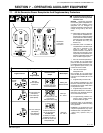
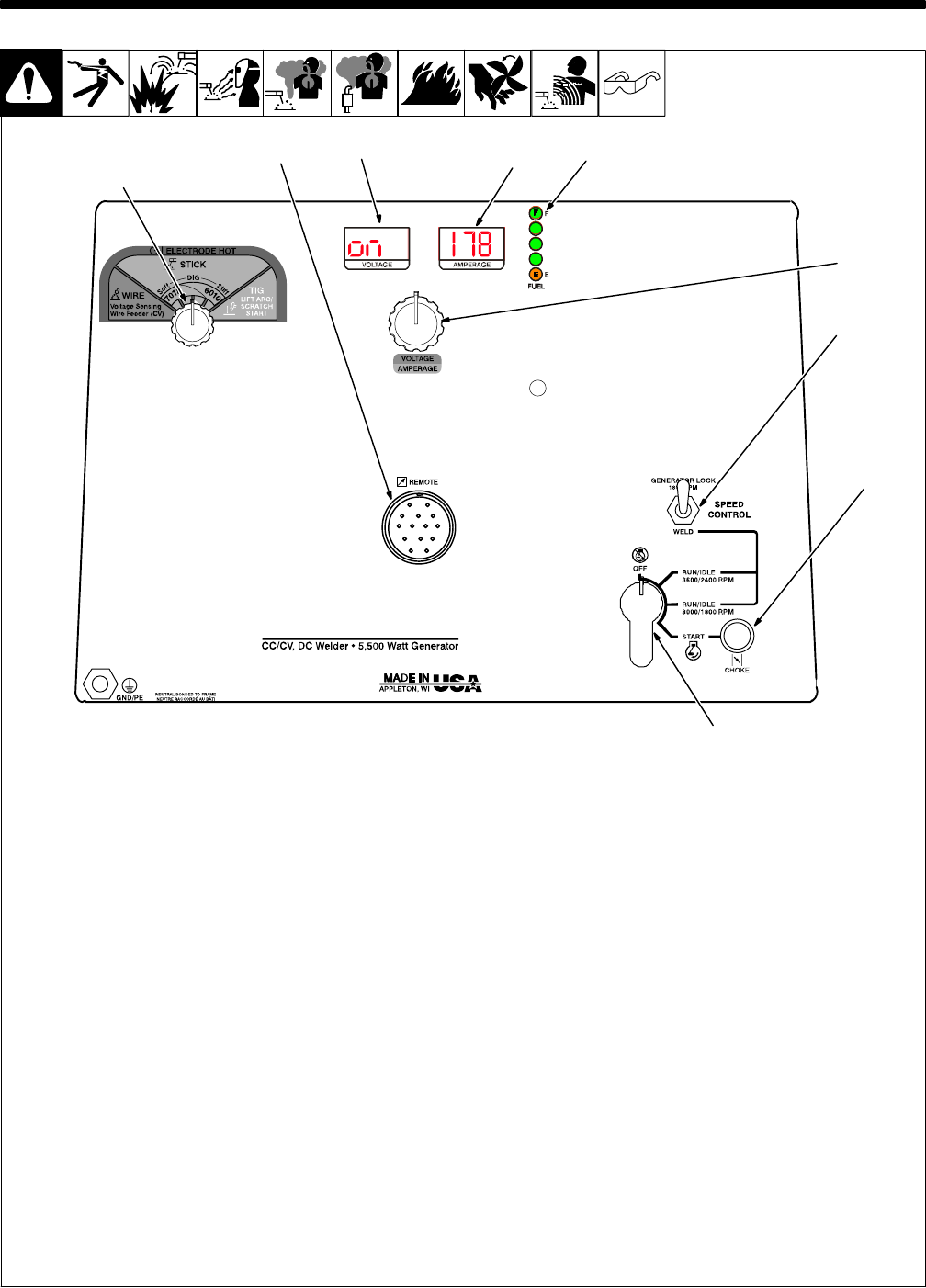
SECTION 6 − OPERATING WELDING GENERATOR
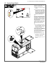
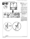
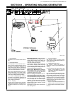
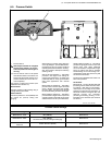
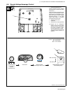
6-1. Front Panel Controls
2
1
4
3
Ref 216 172-D
7
5
6
8
9
1 Process Switch
See Section 6-5 for Process switch informa-
tion.
2 Remote Receptacle
Use receptacle to connect remote control.
When a remote voltage/amperage control is
connected to the Remote receptacle, the
Auto Sense Remote feature automatically
switches voltage/amperage control to the re-
mote control (see Sections 5-7 and 6-8).
With remote voltage/amperage control con-
nected, weld output in CC mode is deter-
mined by a combination of front panel and re-
mote control voltage/amperage settings.
If no remote voltage/amperage control is
connected to the Remote receptacle, the
front panel Voltage/Amperage control ad-
justs voltage and amperage.
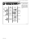
3 And 4 Displays
Displays can show weld process information
(voltage and amperage) or maintenance in-
formation (hourmeter or oil change count-
down).
Meter Weld Functions: In Wire mode, Volt-
meter displays preset weld voltage when not
welding. Meters display actual voltage and
amperage when welding and for five sec-
onds after welding has stopped.
In Stick and TIG modes, Voltmeter reads ON
and Ammeter displays preset amperage
when not welding. Meters display actual volt-
age and amperage when welding and for five
seconds after welding has stopped.
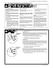
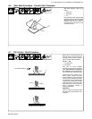
Meter Engine Maintenance Functions:
Meters display engine hours when Engine
Control switch is in the Run/Idle 3600/2400
position but engine is not running.
Meter Oil Change Countdown: With en-
gine off, place Engine Control switch in Run/
Idle 3000/1800 position to see hours before
next recommended oil change. Oil change
hours start at 100 (fresh oil) and count down
to 0 (oil change due). The meters display
negative (−) hours if 100 hours is exceeded.
After changing oil, reset counter by cycling
Engine Control switch between Run/Idle
positions three times.
Place Engine Control switch in Off position
after reading meters.
5 Fuel Level Indicator
With Engine running or Engine Control
switch in either Run/Idle position, LED’s indi-
cate fuel left in tank.
6 Voltage/Amperage Control
Use control to select weld voltage or
amperage. Control may be adjusted while
welding.
. For maximum weld output (above 220
Amps), run unit at 3600 rpm. For weld
output below 220 Amps, operate unit at
3000 or 3600 rpm.
With Process switch in any Stick or TIG set-
ting, use control to adjust amperage. With
Process switch in Wire position, use control
to adjust voltage. When a remote voltage/
amperage control is connected to Remote
receptacle RC4, control sets the maximum
amperage in Stick and TIG modes, but has
no effect in MIG mode.
7 Engine Control Switch (see Section 6-2)
8 Engine Choke Control (see Section 6-2)
9 Engine Speed Control Switch (see Sec-
tion 6-2)