


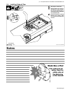
. A complete Parts List is available at www.MillerWelds.com
OM-4430 Page 25
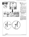
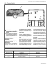
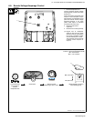
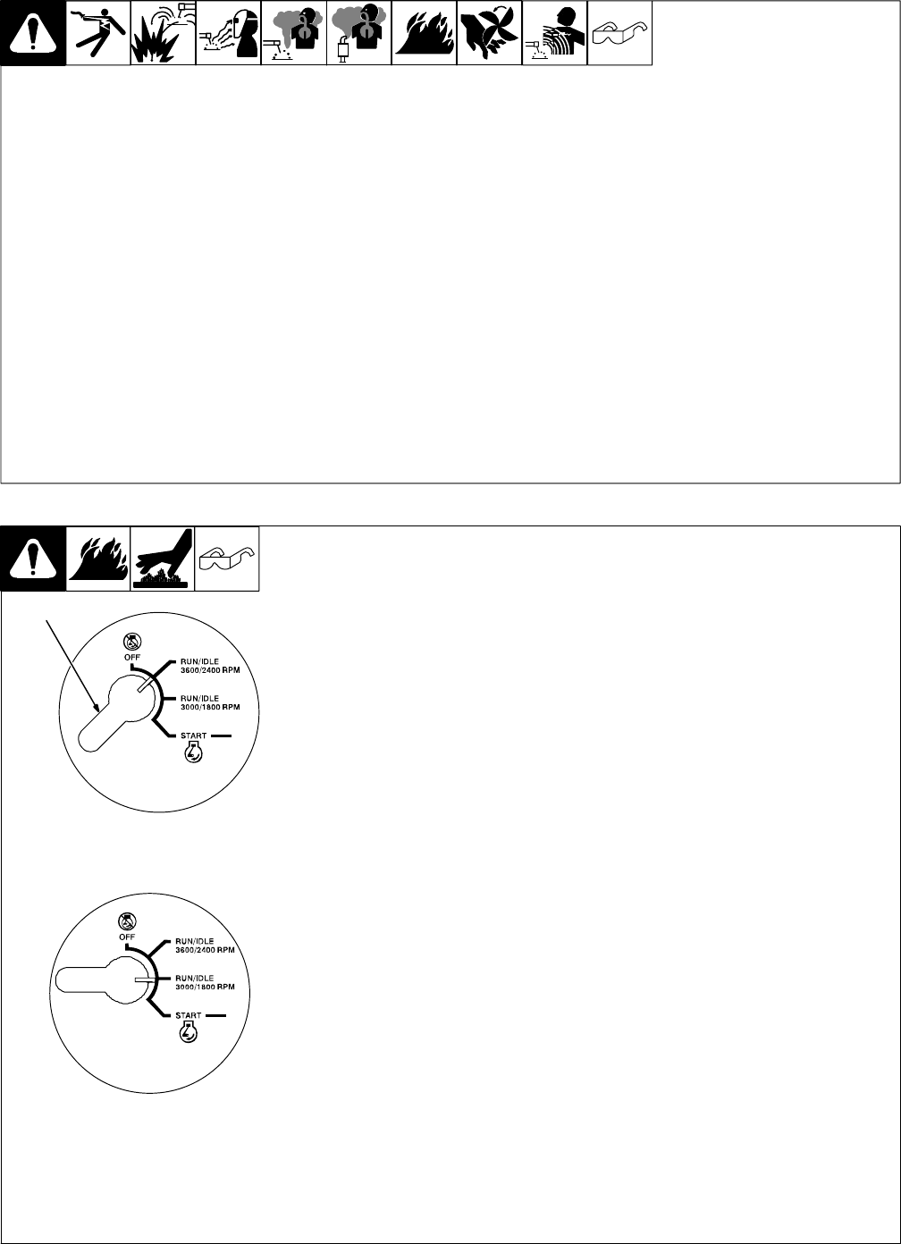
6-2. Description Of Engine Controls (See Section 6-1)
Engine Control Switch
Use switch to start engine, select speed, and
stop engine. Use switch in combination with
Engine Speed Control switch to select en-
gine speed.
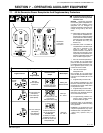
In Run/Idle 3600/2400 RPM position, engine
runs at 2400 rpm no weld load and 3600 rpm
under weld load.
In Run/Idle 3000/1800 RPM position, engine
runs at 1800 rpm no weld load and 3000 rpm
under weld load.
In either position, engine speed is deter-
mined by weld load and position of Engine
Speed Control switch.
. Generator power is available at recep-
tacles RC1 and RC2 only at 1800 rpm.
If generator is not locked at 1800 rpm,
engine speed increases in response to
weld load and generator power output
stops at receptacles RC1 and RC2.
Generator power load does not affect
engine speed.
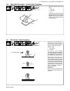
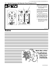
Engine Choke Control
Use control to change engine air-fuel mix
when starting engine.
To Start: pull out choke and turn Engine
Control switch to Start position. Release
switch and slowly push choke in when
engine starts.
With Speed Control switch in Weld, the
engine starts at 3000 rpm and remains there
for two minutes. Engine speed then reduces
to 2000 rpm.
The engine speed reduces from 3000 rpm to
2000 rpm when the Speed Control switch is
toggled within the first two minutes of
operation and no load is applied.
When an auxiliary power load is applied to 60
Hz receptacle RC1 or RC2, engine speed
reduces to 1800 rpm.
. If the engine does not start, let the
engine come to a complete stop before
attempting restart.
. During cold weather some gasoline en-
gines encounter difficulties that are easi-
ly remedied. See Section 6-3 and 8-7.
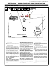
To Stop: turn Engine Control switch to Off
position.
Engine Speed Control Switch
Use switch to control engine auto idle func-
tion. Place switch in Generator Lock position
when not welding to lock engine speed at
1800 rpm for generator power at 60 Hz ac re-
ceptacles RC1 and RC2 (generator power is
always available at 60−120 Hz receptacle
RC3. See Section 7-2.)
Place switch in Weld position to allow engine
speeds to be determined by position of En-
gine Control switch. The Speed Control
switch is not needed at start−up.
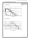
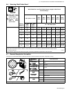
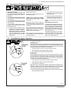
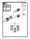
6-3. Cold Weather Engine Operation
Ref. 216 172
1 Engine Control Switch
Carburetor Icing
Carburetor icing causes the unit to drop below the normal idle speed and then stall.
This condition occurs when the temperature is near freezing and the relative humid-
ity is high. Ice forms on the throttle plate and inner bore of the carburetor. The engine
typically restarts without problems but soon stalls again.
S Treat gasoline with a fuel de−icer product (isopropyl alcohol).
S Place the Engine Control switch in the Run position.
S Run engine only when expecting to frequently load it.
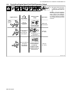
Breather Icing
Oil breather/pulse line icing occurs in severe cold (continuously below 0_F). Mois-
ture accumulates in the oil from piston ring blow−by if the engine is extensively idled.
This may cause vacuum line freezing, oil breather tube freezing or ice in the carbure-
tor. All of these cause operating problems. Due to ice in the lines, the engine may
not restart until it is warmed to above freezing.
S Load engine and reduce idle times to prevent engine shutdowns.
S Use an electric fuel pump to avoid pulse line freezing.
S Install engine cold−weather kit.
Kohler offers a kit for cold weather operation. Contact engine manufacturer for kit
information (1-800-544-2444). The user can install these kits. The kit pulls heated
air from the muffler surface into the carburetor and shuts the cold air off. This in-
creases engine temperature during operation in both idle and high speed.
. When the ambient temperatures become warmer (above 45_F) the air flow will
have to be returned to normal.
1
Frequently
Loaded
Infrequently
Loaded