


OM-225 590 Page 21
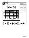
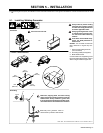
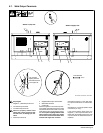
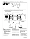
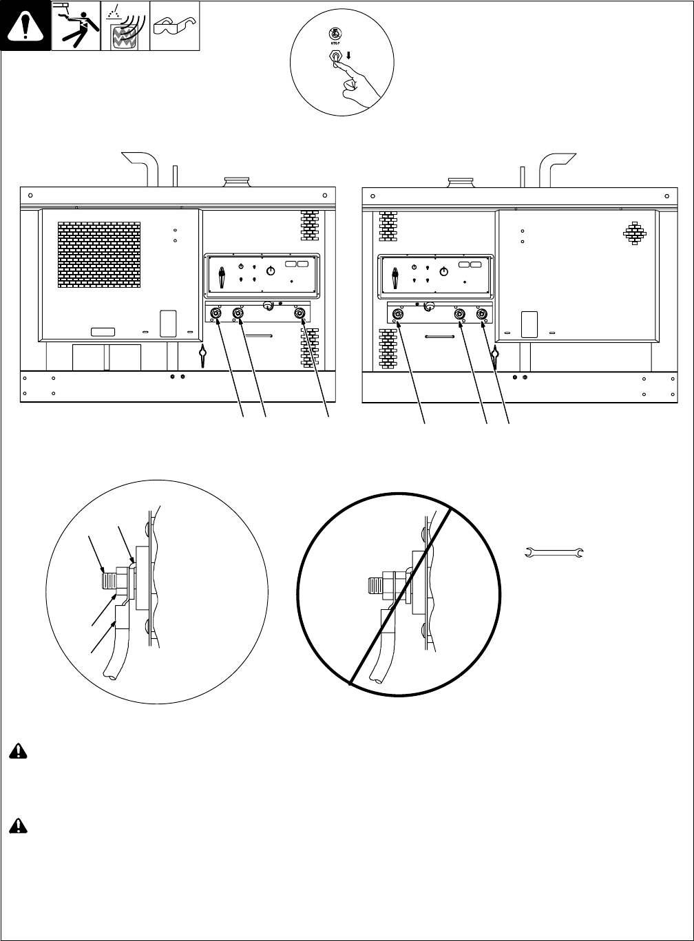
5-7. Weld Output Terminals
Ref. 225 543 / 802 292-A / 803 788-A
! Stop engine.
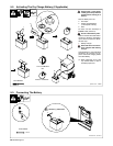
1 Negative (−) Weld Output Terminal
2 CV Weld Output Terminal
3 CC Weld Output Terminal
! Failure to properly connect weld
cables may cause excessive heat
and start a fire, or damage your ma-
chine.
4 Weld Output Terminal
5 Supplied Weld Output Terminal Nut
6 Weld Cable Terminal
7 Copper Bar
Remove supplied nut from weld output ter-
minal. Slide weld cable terminal onto weld
output terminal and secure with nut so that
weld cable terminal is tight against copper
bar. Do not place anything between weld
cable terminal and copper bar. Make
sure that the surfaces of the weld cable
terminal and copper bar are clean.
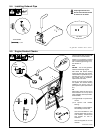
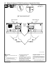
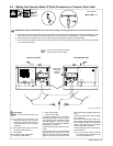
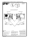
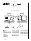
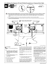
See Sections 5-8 thru 5-13 for dual opera-
tor output connections for CC and CV weld-
ing.
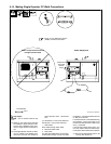
See Section 5-14 for single operator output
connections (CC only).
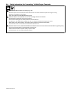
If unit has the Polarity switch option, the
Negative (−) weld output terminals are la-
beled Work receptacles and the CC weld
output terminals are labeled Electrode re-
ceptacles.
Tools Needed:
3/4 in
Welder B (Right) Side
123
Welder A (Left) Side
123
7
5
6
Do not place
anything between
4
weld cable terminal
and copper bar.