


OM-225 590 Page 44
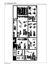
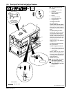
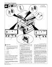
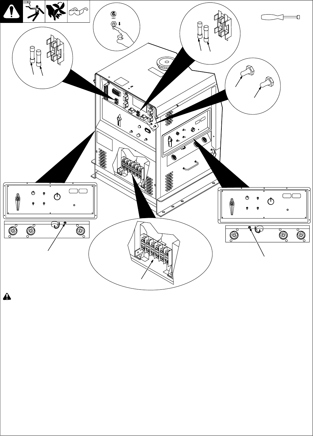
8-10. Circuit Protection
Ref. 802 300 / Ref. 802 292-A
! Stop engine.
. When a supplmentary protector or fuse
opens, it usually indicates a more seri-
ous problem exists. Contact Factory
Authorized Service Agent.
1 Fuse F1
2 Fuse F2
3 Fuse F3
4 Fuse F4
Open front panel.
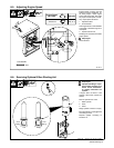
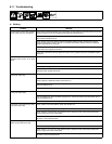
Fuse F1 protects the exciter excitation
winding. If F1 opens, there is no weld or
generator power output on both sides.
Fuse F2 protects the exciter main field ex-
citation winding. If F2 opens, there is no
weld output on both sides.
Fuse F3 protects Welder A (left) control
board PC1. If F3 opens, Welder A (left) weld
output stops.
Fuse F4 protects Welder B (right) control
board PC1. If F4 opens, Welder B (right)
weld output stops.
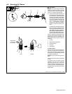
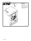
5 Supplementary Protector CB5
6 Supplementary Protector CB6
7 Supplementary Protector CB7
8 Supplementary Protector CB8
Supplementary Protector CB5 protects the
24 volt and 115 volt ac output to Welder A
(left) remote receptacle RC9. If CB5 opens,
Welder A (left) RC9 24 and 115 volt ac out-
put stops.
Supplementary Protector CB6 protects the
24 volt and 115 volt ac output to Welder B
(right) remote receptacle RC8. If CB6
opens, Welder B (right) RC8 24 and 115 volt
ac output stops.
Supplementary Protector CB7 protects
field current regulator board PC4. If CB7
opens, weld and generator power output on
both sides stops.
Supplementary Protector CB8 protects the
generator field flashing circuit. If CB8
opens, weld and generator power output
may continue if generator maintains excita-
tion. Weld and generator power output
stops if generator requires field flashing cir-
cuit to restore excitation.
Press button to reset supplementary pro-
tector.
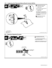
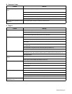
9 Fuses F11, F12, F13, F21, F22, F23
These fuses protect the weld stator wind-
ings. If fuse F11, F12, or F13 opens, Welder
B (right) side output is erratic or low. If fuse
F21, F22, or F23 opens, Welder A (left) side
output is erratic or low.
10 Thermostats TP3 And TP4 (Internal −
Not Shown)
Thermostat TP3 protects Welder A (left)
SR2 rectifier and TP4 protects Welder B
(right) SR3 rectifier from overheating. If
TP3 or TP4 opens, Welder A (left) or Welder
B (right) weld output stops and the High
Temp. Shutdown light goes on. Wait fifteen
minutes for module to cool and thermostat
to automatically reset. Reduce amperage,
voltage, or duty cycle before welding.
Tools Needed:
3
4
7
8
5
6
1
2
9