


OM-225 590 Page 45
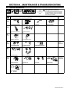
8-11. Troubleshooting
A. Welding
Trouble Remedy
No weld output on either side; generator
power output okay at ac receptacles.
Place Output (Contactor) switches in On (Hot) position, or place switches in Remote position and connect
remote contactors to remote receptacles RC8 and RC9 (see Section 6-3).
Unit overheated (High Temp. Shutdown light goes on); wait several minutes for thermostat(s) TP3 and
TP4 to reset (see Section 8-10).
Check position of Process Selector switches and Welder Selector switch. All weld output stops if
either Process Selector switch is placed in CV position when Welder Selector switch is in Welder B
position (see Sections 6-1 and 6-3).
Check fuse F2, and replace if open (see Section 8-10). Have Factory Authorized Service Agent
check field current regulator board PC4.
Have Factory Authorized Service Agent check field current regulator board PC4 and Welder Selector
switch S2.
No weld output on either side and no
generator power output at ac recep-
tacles.
Disconnect equipment from generator power receptacles during start-up.
Check fuse F1, and replace if open (see Section 8-10).
Reset supplementary protectors CB7 and/or CB8 (see Section 8-10).
Have Factory Authorized Service Agent check brushes and slip rings, field excitation circuit, rotor, stator,
and field current regulator board PC4.
No Welder A (left) weld output; Welder B
(right) weld output okay.
Check fuse F3, and replace if open (see Section 8-10).
Check position of Welder Selector switch. Welder A (left) weld output stops when Welder Selector
switch is placed in Welder B position (see Section 6-1).
Unit overheated (High Temp. Shutdown light goes on); wait several minutes for thermostat(s) TP3 to
reset (see Section 8-10).
Have Factory Authorized Service Agent check Welder A (left) contactor circuit.
No Welder B (right) weld output; Welder
A (left) weld output okay;
Check fuse F4, and replace if open (see Section 8-10).
Unit overheated (High Temp. Shutdown light goes on); wait several minutes for thermostat(s) TP4 to
reset (see Section 8-10).
Have Factory Authorized Service Agent check Welder B (right) contactor circuit.
Low Welder A (left) weld output; Weld-
er B (right) output okay.
Check position of Process Selector switch (see Section 6-3).
Increase Amperage/Voltage control setting.
Check fuses F21, F22, and F23, and replace if open. If fuse(s) are open, have Factory Authorized
Service Agent check main rectifier SR2.
Have Factory Authorized Service Agent check main rectifier SR2, synchronization transformers T5,
T6 and T7, and control board PC1.
Low Welder B (right) weld output;
Welder A (left) weld output okay.
Check position of Process Selector switch (see Section 6-3).
Increase Amperage/Voltage control setting.
Check fuses F11, F12, and F13, and replace if open. If fuse(s) are open, have Factory Authorized
Service Agent check main rectifier SR3.
Have Factory Authorized Service Agent check main rectifier SR3, synchronization transformers T8,
T9 and T10, and control board PC5.