


OM-225 590 Page 36
SECTION 7 − OPERATING AUXILIARY EQUIPMENT
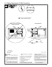
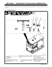
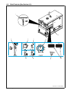
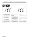
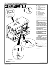
7-1. 120 Volt And 240 Volt Duplex Receptacles
190 376
! Be sure equipment connected to the
240 V receptacles is GFCI-pro-
tected.
. Generator power is not affected by
position of Welder Selector switch.
. 4 kVA/kW generator power output is
shared by all receptacles.
1 240 V 20 A AC Receptacle RC1
2 120 V 20 A AC GFCI Receptacle
GFCI 1
3 240 V 20 A AC Receptacle RC2
4 120 V 20 A AC GFCI Receptacle
GFCI 2
Receptacles supply 60 Hz single-phase
power at weld/power speed.
If a ground fault is detected, the GFCI re-
ceptacle(s) circuit opens to disconnect the
faulty equipment and the GFCI Reset but-
ton pops out. Check for damaged tools,
cords, plugs, etc. connected to the recep-
tacle. Press button to reset receptacle and
resume operation.
. At least once a month, run engine at
weld/power speed and press Test but-
ton to verify GFCI is working properly.
5 Supplementary Protectors CB1 And
CB2
6 Supplementary Protectors CB3 And
CB4
CB1 and CB2 protect RC1 and GFCI 1 from
overload. If CB1 or CB2 opens, RC1 does
not work. 120 volts may still be present at
RC1. If CB2 opens, GFCI 1 does not work.
Press button to reset.
CB3 and CB4 protect RC2 and GFCI 2 from
overload. If CB3 or CB4 opens, RC2 does
not work. 120 volts may still be present at
RC2. If CB4 opens, GFCI 2 does not work.
Press button to reset.
. If a supplementary protector continues
to open, contact Factory Authorized
Service Agent.
Maximum output from each 120 volt GFCI
receptacle is 2.4 kVA/kW. Maximum output
from each 240 volt duplex receptacle half is
4.0 kVA/kW.
Total combined output from all receptacles
is 4 kVA/kW.
EXAMPLE: If 12 A is drawn from RC1, only
9 A is available at GFCI 1:
(240 V x 12 A) + (120 V x 9 A) = 4.0 kVA/kW
. Generator power is not affected by
weld output.
152
3
64